Ah yes, the 555 piano project. Be it the Atari Punk Console, or some other 555 based synthesizer, Hackers just love to hear what the 555 can do when attached to a few passives and a speaker. It’s a sound to behold. But for [Berna], that wasn’t quite enough! Below the break, you can see his creation, called the Acordeonador.
A portmanteau of the Spanish words for “Accordion” and Generator”, the Acordeonador does what no project we’ve seen so far can do: It turns a CD drive into a generator for a 555 based synthesizer.
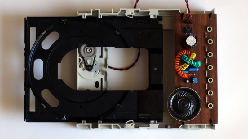
To give the Acordeonador a more analog feeling, a large 4700uf electrolytic capacitor stores just enough energy to make the music generation more than an on/off affair. It’s a great effect, and it works well! Not being one to leave any details out, [Berna] prototyped the build on perf board and then covered the board in what appears to be an wood grained contact paper, giving it that 1970’s dual keyboard electric organ feel.
It really just goes to prove that a 555 project can be the source of a great time! Hackaday is rife with 555 projects, but if you enjoy this, be sure to check out The Most Important Device In the Universe, which is of course powered by a 555.


Okay, if this is an entry in the 555 Contest, I may as well quit now! B^)
Kudos for the title
Love it. As a kid a favorite was a battery (literally an “A” battery), speaker and motor in series and pitch was controlled by gripping the motor spindle (gear). That was in the pre-555 era. Says a lot about my (lack of) musical ability. My parents survived.
This has it all. The CD’s DC brushed motor as an AC generator, then rectifier / power supply and then 555, buttons shorting series resistors and speaker driven by the 555 driven (buffered) output. There’s a bit of calculation that went on to get the right resistor values.
There’s a lot happening that isn’t obvious here. If I were to do this with a transistor astable multi-vibrator then the frequency of the sound would rapidly increase as the supply voltage dropped so that the base bias drive voltage wasn’t much more than the the ON Vbe of the transistors. This doesn’t happen with the 555 because the 555 design has been very careful to make it as Vcc independent as possible.
It would sound much better with a saw wave than a square wave or even a sine wave. The saw wave exists but it’s in a part of the circuit that doesn’t have enough drive current to drive a speaker. Perhaps one or two of the (UC/LMC) 555’s friends: the (UC / uA) 741’s op-amps as drive with two bipolar transistors and maybe one or two as an integrator – square to saw to sine. Perhaps an op-amp with lower voltage operation would be needed.
And YES! This is definitely a HACK!
brilliant!!!
CD quality music!
Great device., especially the self powering. Presumably it is the speaker that requires the most power, so I wonder if you could hook up 7 555 timers in parallel to common speaker drive and get chords on pretty much the same power?
The original is here –
https://hackaday.io/project/183278-acordeonador
“in parallel” well that is simple to say. The output of the 555 is a square wave. The power consumption is the speaker transitioning from one state (0 or 1) to the other state (1 or 0) respectively.
The power consumption of the 555 itself is negligible in this circuit especially if you use a CMOS 555.
For more channels (polyphonics) the problem becomes one of power consumption or signal mixing depending on how you mix the signals. Or both.
If you just mix all the 555 square wave outputs together with resistors then you end up with an analogue signal and would need a class “D” amplifier to conserve power consumption. Perhaps that could be done with another 555 as a class “D” mixer amp.
Alternatively you cold digitally mix the signals. Logically it would evaluate to a 7 input (one octave) XOR gate. In practice two CMOS ICs – quad 2 input XOR’s may do it (CD4070). Then the signal is still digital, just a “more complex” square wave with many more transitions. But remember – it’s the transitions driving the speaker that consume the power.
On a bit of a side topic. People often refrain from using multiple 555 in musical instruments do to the need to continually adjust / trim / tune the oscillators due to component thermal drift. Resistors don’t drift significantly with temperatures that humans exit at. The resistors used in this project are 5% tolerance and there is only one trimmer (tuning) resistor for the 7 frequencies. That is because there is only one capacitor in the RC circuit and it’s that capacitor that has thermal drift that needs to be compensated for.
The 555 will work equally well with RC, LC or LR circuits for astable oscillation. Inductors (L) don’t drift with temperature, you just have to make sure they don’t move around. We used to do this by winding them on a cylindrical core like a nail, having the winding start at one end and ending at the other then the wires soldered into a circuit board would hold it in place. For finer winding wire we covered the inductor over with paraffin. Candle wax is paraffin with a hardener added so candle wax would be even better than paraffin.
Also an op-amp can be configured as an integrator. An integrator converts a symmetrical square wave to a symmetrical saw wave and it converts a symmetrical saw wave to a sine wave. It does this extremely accurately and this type of circuit was used in test equipment like noise and distortion meters because the end sine wave is very clean and at the same time you can have a large sweep frequency because your starting with a digital square wave.
Point being that sine and saw waves sound much better than square waves for a musical instruments.
Hackordion!