If you want to move a pen (or a CNC tool, or a 3D printing hot end) in the X and Y plane, your choices are typically pretty simple. Many machines use a simple cartesian XY motion using two motors and some sort of linear drive. There’s also the core-XY arrangement where two motors move belts that cause the head to travel in two directions. Delta printers use yet another arrangement, but one of the stranger methods we’ve seen is the dual disk polar printer which — as its name implies — uses two rotating disks.
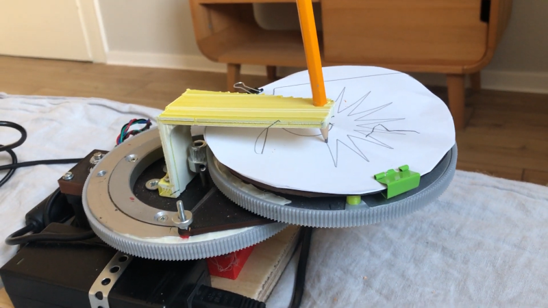
The unique mechanism uses one motor to rotate a disk and another motor to rotate the entire assembly. The print head — in this case a pencil — stays stationary. as you can see in the video below.
We enjoyed [heinz’s] write up and that he cited his influences. There’s the Theta printer. There was also a proposal on the RepRap forum back in 2006. But this plotter is his.
We’ve often thought of using a rotary Z axis for 3D printing, although that would take some approximation math since each layer would really be a spiral depending on where you were in the rotation. However, that doesn’t help you if you wanted to make a plotter or other flat machine like a laser engraver. This setup would work for those cases, but we aren’t sure if there is any real benefit compared to existing schemes. Except that it looks cool in motion.
If you want to learn more about core-XY, we’ve got some reading for you. The Theta printer was part of one of our contests, so you can read more about it, too.


Isn’t that a variation on the scara mechanism? Here the table/bench is moving, instead of the arm?
That’s what I was thinking. The only difference is which part is stationary.
Now all we need is a variation where the center pivot point is stationary and both the workpiece and the tool move!
One tricky thing about polar designs is that the (stylus / nozzle) needs to be aligned very accurately in order to meet the rotating plate’s center. If it doesn’t meet the center, then no amount of rotation will be able to get it there.
That’s not true at all.
The kinematics are intersecting arc trigonometry. If the end effector is not at center and it is intended to be so then the accuracy will be out. Alternatively if the end effector is off center and it’s intended to be so then all is fine.
If the end effector “is not at center” then you have a spot right in the middle in the drawing area that can never be reached. Yuck!
Now I see what you actually meant.
It just makes things harder (including the reverse kinematics) if you place the end effector at half the diameter of the rotating disk. Ideally the end effector should be past the the disks pivot point. Most commonly the end effector is place at the center of the quadrant opposite the arc pivot.
LOL, I bombed out twice. I was thinking parallel kinematics but this is simply a SCARA.
Whatever is old is new again…
The Rθ plotter (as the polar plotter was termed) the basic trig behind it and the problem of resolution was described in the article ‘More on Inexpensive Plotters’ way back in BYTE October 1977 page 58:
https://archive.org/details/byte-magazine-1977-10/page/n59/mode/2up
Nicely dug up! Haven’t seen that before. Did you just search the archive or did you remember something like that from the magazine?
Remembered it :) Due to lack of space I gave away most of the BYTEs and other computer magazines I used to collect in the 80s and 90s twenty years ago but kept most of the ones from the 70s, and had looked at them so many times that even now I still recall what many of the articles were. These days they are on archive.org which is wonderful.
I even built the odd hardware and software project from them, back then.
One of the benefits of a design like this vs cartesian is an absence of aliasing when doing circular work. Try using a mill, absent a rotary table, to create a cylinder and then do the same on a lathe and note the difference in accuracy and surface finish. There could arguably be some additional benefits if you’re using a worm gear to drive the tables compared to traditional leadscrews such as inability to backdrive.
Of course the inverse is true as well, namely that linear work will most probably be less accurate than a cartesian setup.
Is it just me or does anyone else think this mechanism could be used for decorating cakes?
I saw a cake decorator that was a little similar and very interesting in how it worked.
It to had a fixed end effector with the nozzle for icing or whatever the decoration is.
The cake dish was modified to have gear teeth all around the circumference so it was like a big cog.
To the left and right of where the cake plate went was a belt held straight between a stepper and a pulley, one assembly on each side.
If the belts went the same direction then the plate would go (away) up or down (towards). If they went different directions then the plate would rotate.
here you go https://www.youtube.com/watch?v=EOOtx4T7OcA
Nice, that’s a cool design, thank your both for sharing!
Now, how about a big polar plotter to move a magnet under a round sand table?
Somewhere in the ’80s or ’90s the dutch version of Elektor (Elektuur) presented a project called “Tanbo” (Tangentiale Boormachine) The setup was pretty much exactly the same as this and it’s goal was to drill holes in PCB’s. It could even be extended with a second arm, so it could drill two holes at the same time, or hold two different sizes of drills.
It had quite nifty differential planetary gearboxes. But for a thing made out of plastic and still with a pretty steep price point my guess was there were not many sold.
In those days the Open Source movement was not so widespread as it is now. You had do buy pre-burned microcontrollers or spend months writing your own firmware.
Oof, I love that!
Here is the articel https://www.avrfreaks.net/sites/default/files/Elektor.pdf
Would never have found that without you pointing it out. Thanks!