

Introduction: Portable Soldering Station From Recycled Material. / Estación De Soldadura Portátil Hecha Con Material Reciclado.


Dad was a great artist and adventurer as much as he was a big fan of DIY culture. Him alone made lots of modifications to the house which include furniture and closet improvement, antique lamp upcycling and even modified his VW kombi van for traveling.
Even before he got ill, he left me his tools knowing I would put them to good use. ¡Here’s for you, dad!
ESPAÑOL:
Papá fue un gran artista y aventurero tanto como un gran fan de la cultura de “hágalo usted mismo”. Él solo hizo muchas modificaciones a la casa, las cuales incluyen el mejoramiento de muebles y closets, reciclado y mejoramiento de lámparas antiguas, e incluso modificó su combi para viajar.
Aún antes de enfermar, papá me dejó sus herramientas sabiendo que les daría un buen uso. ¡Va por ti papá!
Step 1: Search and Plan / Buscar Y Planear.


I just recently finished the instructables electronics class, so before I plunged myself into action, I needed a proper space to do so. Checking around the workshop, I found plenty of reclaimed wood and lots of scraps and unsorted pieces of dad’s old projects. This is what I chose:
- MDF board. It had an ugly water stain, though. I figured I could sand it away later.
- Square thin dowel.
- Round stick.
- Three jars filled with all sorts of nails, washers, screws and nuts.
- A roll of hard plastic covering.
- Alligator clips.
- A 12v 700 mA transformer from an unknown appliance.
- A led stripe harvested from a broken netbook screen.
- Two 470 ohm resistors.
- Rubber feet from an old blender.
- Recycled red and black wires.
- Assorted wood clippings.
- Thin soft rubber tube.
- Old computer fan.
- Large sponge.
- Cap from a medium size jam jar.
- Hot glue sticks.
- Big spring.
- Small clear tape.
-Double face tape.
- Sandpaper (80 and 1000 grit).
- DPDT double switch set.
Tools:
- Drill and bits.
- Hand saw.
-Chisel.
- Hammer.
- Pliers.
- Carpenter’s square.
- A set of screwdrivers.
- A set of hole saws.
- Vice. (You can use whichever vice you have at hand).
- Soldering iron and solder.
- Pyrograph.
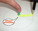
Before making anything, I decided to take a time to imagine what I wanted, picture it in my mind and put it on paper. After doodling a bit, I was ready to work.
ESPAÑOL:
Recientemente terminé el curso de electrónica en Instructables, así que antes de sumergirme de lleno en la acción, decidí que necesitaba un lugar adecuado para ello. Revisando el taller, encontré mucha madera reclamada y sobrantes y piezas sueltas de los viejos proyectos de papá. Esto es lo que escogí:
- Tablón de aglomerado MDF. Tenía una fea mancha de agua, pero pensé en quitársela después con una lijada.
- Varilla de madera cuadrada.
- Palito redondo.
- Tres frascos llenos con toda clase de clavos, tornillos, rondanas y tuercas.
- Un rollo de cubierta de plástico duro.
- Pinzas de caimán.
- Un transformador de 12v 700mA de un aparato desconocido.
- Una tira de leds obtenida de la pantalla de una netbook rota.
- 2 resistencias de 470 ohms.
- Patas de goma de una licuadora vieja.
- Cables de color negro y rojo, reciclados.
- Pedacería surtida de madera.
- Tubo flexible de plástico.
- Ventilador de una computadora vieja.
- Esponja grande.
- Tapa de una botella mediana de mermelada.
- Varillas de silicón.
- Resorte grande.
- Cinta transparente.
- Cinta doble cara.
- Lija (calibres 80 y 1000).
- Switch doble, 2P2T (Dos polos, dos tiros).
Herramientas:
- Taladro y brocas.
- Serrucho.
- Cincel.
- Martillo.
- Pinzas.
- Escuadra de carpintero.
- Juego de Desarmadores.
- Juego de sierras de corona.
- Prensa (Pueden usar cualquiera que tengan a mano).
- Cautín y soldadura.
- Pirógrafo.
Antes de hacer nada, decidí tomarme un tiempo para imaginar lo que quería, dibujarlo en mi mente y ponerlo en papel. Después de garabatear un poco, estaba lista para trabajar.
Step 2: Base and Third Hand / Base Y Tercera Mano.


First cut the MDF to obtain a 55 cm long, 30.5 cm wide board for the base, then measured and cut the square dowel to get four 10cm pieces. Sanded the board and the dowel pieces, then drilled a hole at the bottom of each dowel. From one of the jars I got a small threaded aluminum tube (I think it was from a discarded lamp), got two screws to fit in and cut the heads. With the help of pliers, turned in a screw in the hole of each of two of the dowel pieces, letting half a screw in and half out. For the other two sticks, found two slim screws and placed them in, measuring carefully to let enough space to adjusting the alligator clamps by pressure with the pliers. Took a clamp dowel piece and a screw dowel piece and overlapped the unworked ends, clamped them with the drill press vice and performed a hole in both at the same time to reduce the error margin to minimum. Passed through a screw and secured the union with a wing nut. Repeated the same for the other pair. Back to the base, measured 9 cm from the left side in and 6 cm to the top in, and marked. Then measured 10 cm from the mark to the right and marked again. This is where the arms of the third hand would be placed. Drilled the holes, took the aluminum tube, cut it in half and inserted each piece in a hole with the help of a hammer. The drilled holes where slightly smaller than the tubes, so pressure would secure them in place without any glue. Finally, turned the screws into the base to secure the arms. Now I had an adjustable, detachable third hand.
To finish the base, measured 1 cm from each corner of the back of the board and drilled a hole to place the rubber feet. Cut an 8X8 cm square from the plastic covering and glued it with some hot glue under the third hand to protect the wood from possible hot falling solder.
ESPAÑOL:
Primero, para la base, corté el aglomerado para obtener una tabla de 55 cm de largo por 30.5 cm de ancho, después medí y corté el bastón cuadrado para obtener cuatro piezas de 10 cm cada una.
Lijé la tabla y las piezas y perforé un hoyo en el extremo de cada uno de los bastones. De uno de los frascos, obtuve un tubo pequeño de aluminio con cuerda (creo que era de una lámpara desechada),
conseguí dos tornillos que le quedaran y les corté la cabeza. Con la ayuda de unas pinzas le di vuelta a los tornillos para colocarlos dentro de dos de los bastones, dejando medio tornillo dentro y medio fuera.
Para los otros dos bastones conseguí un par de tornillos delgados y los atornillé teniendo cuidado de dejar suficiente espacio para ajustar los caimanes por presión con ayuda de las pinzas.
Tomé una de las piezas con el tonillo decapitado y otra con un caimán, empalmé los extremos sin trabajar, los aseguré con la prensa para taladro y realicé un orificio en ambos al mismo tiempo para reducir el margen de error al mínimo.
Pasé un tornillo por ahí y aseguré la unión con una tuerca de mariposa. Hice lo mismo para el otro par.
De regreso a la base, medí 9 cm del lado izquierdo hacia adentro y 6 cm de la parte de arriba hacia abajo e hice una marca. De ahí medí 10 cm hacia la derecha e hice otra marca; ahí es donde colocaría los brazos de la tercera mano. Perforé los hoyos, tomé el tubo de aluminio, lo corté por la mitad e inserté cada parte en un hoyo con la ayuda de un martillo. Las perforaciones eran ligeramente más pequeñas que los tubos para que quedaran asegurados por presión sin necesidad de pegamento.
Finalmente enrosqué los tornillos a la base para asegurar los brazos. Ahora tenia una tercera mano desmontable y ajustable. Para terminar la base, medí 1 cm desde cada una de las esquinas de la parte trasera de la tabla y perforé para colocar las patas de goma. Corté un cuadrado de 8X8 cm de cubierta de plástico y lo pegué con silicón en el área justo debajo de la tercera mano para proteger la madera de posibles gotitas de soldadura caliente que pudieran caer.
Step 3: Soldering Iron Stand / Base Para Cautín.

Cut 8 cm out from the big spring with pliers, crooked the end to a more or less 45° angle, measured 13 cm from the right end of the base in and 6 cm from the top right in and drilled a hole. Placed the spring and secured it with washers and a bolt. Hot glued the cap from the jam jar to the base, just back from the spring, cut a circle of sponge to fit in the cap for a soldering iron tip cleaner. For it to work properly, I would have to wet the sponge a little every time I start working and place it to dry outside the cap when I’m finished.
ESPAÑOL:
Corté 8 cm del resorte grande con las pinzas y doblé la parte final a un ángulo de 45° más o menos, medí trece centímetros de la parte derecha de la base hacia adentro y seis centímetros de la parte de arriba hacia adentro e hice una perforación. Coloqué el resorte y lo aseguré con un tornillo grande y rondanas. Pegué con silicón la tapa del frasco de mermelada a la base, justo detrás del resorte, corté un círculo de esponja que cupiera dentro para hacer un limpiador de punta para el cautín. Para que funcione correctamente, tendré que mojar la esponja un poco cada vez que comience a trabajar y sacarla a secar cuando termine.
Step 4: Fume Extractor / Extractor De Humo.


After some thought, I decided to give the fume extractor some height, basically because I felt if placed directly on the base, it can get in the way or cause some distraction when working. For a stand, used a pair of wood clippings: one was a left over from a round hand rail, adjusted it to 12 cm and drilled a hole in the bottom. The other was a rectangular wood piece 14 cm long 2 cm wide, perfect to support the fan since it fitted nicely. To make the filter: cut four 2cm long pieces from a round stick and drilled a small guide hole at the center of each, attaching them to the fan with screws. Cut four pieces 9 cm long, 2 cm wide from the plastic covering roll to make a filter casing, hot glued each piece to each of the sides of the fan via the small round sticks and reinforced the unions with clear tape. Cut a square sponge to fit the casing and to prevent it to fly away, placed a screw at the end of each round stick and crossed two rubber bands. To secure the fan to the stand, first marked the center of the wood rectangle and drilled to fit a screw, then placed the fan to be centered on the wood rectangle and made a mark on each side, drilled the holes and attached the elastic tube to it with screws and washers, and finally trimmed the excess. I left it a little tight so it could grab the fan firmly. After this, put a screw in the middle hole performed earlier and attached the round dowel to it. Checked for the middle point between the arms of the third hand and from there measured 3 cm to the top end of the board, marked and drilled a hole all the way to the other side to screw the base of the extractor from the bottom. Finally, drilled a hole to pass through the power cables.
ESPAÑOL:
Después de pensarlo un poco, decidí darle al extractor de humo algo de altura, básicamente por que sentía que si lo colocaba directamente en la base podría estorbar o causar alguna distracción al trabajar. Para la base usé un par de pedazos de madera: uno era un desecho de un pasamanos redondo, lo ajusté a que midiera 12 cm y perforé un hoyo en la base. El otro era una pieza rectangular de 14 cm de largo y 2 cm de ancho, perfecta para soportar el ventilador pues embonaban muy bien. Para hacer el filtro: corté cuatro piezas de 2cm cada una de un palito redondo, taladré un hoyo guía en el centro de cada uno y los atornillé al ventilador, después corté cuatro pieza de 9 cm de largo y 2 cm de ancho del rollo de cubierta de plástico para hacer la caja del filtro, los pegué con silicón a los lados del ventilador usando los palitos como soporte y reforcé las uniones con cinta transparente. Corté una esponja cuadrada que cupiera en la caja y, para evitar que saliera volado, coloqué un tornillo en cada uno de los extremos de los palitos y crucé dos ligas. Para asegurar el ventilador al soporte, primero marqué el centro del rectángulo de madera e hice una perforación para poner un tornillo, después coloqué el ventilador para que estuviera centrado sobre este y marqué los extremos, realicé las perforaciones y aseguré el tubo elástico con ayuda de tornillos y rondanas; finalmente corté el exceso. Lo dejé un poco justo para que sujetara el ventilador firmemente. Después de esto, coloqué un tornillo en el agujero del centro que perforé anteriormente y lo aseguré a la varilla redonda de madera, busqué el punto medio entre los brazos de la tercera mano, medí 3cm de ahí hacia arriba y perforé hasta el otro lado para atornillar la base del ventilador desde abajo. Finalmente, hice un hoyo para pasar los cables de alimentación.
Step 5: Lamp's Body / Cuerpo De La Lámpara.


To make the body of the lamp, cut a square piece of the leftover MDF to fit a circle I marked from the cap of one of the screw jars, cut the circle and sand it by hand, clamped the piece in the drill press vice and made a first cut with the biggest available hole saw trying not to cut too deep, then took the smallest and performed a second cut, then removed the material between both cuts to get a cavity. Sanded the space to make it even and drilled a guide hole at the edge of the circle. Measured and cut two pieces from the square dowel, both 12.5 cm long, drilled a guide hole at the end of one of them and did the same as with the third hand arms: took a screw, cut the head and inserted in half way, so that the other half of the screw could adjust to the lamp’s head. Once again overlapped the wood pieces at the unworked ends and drilled a hole in the clean side, both at the same time, passed a screw and secured with a wing nut. I wanted the lamp to have more versatility than the third hand arms, so I made a movable, collapsible base for it by taking three pieces of the square dowel: one small, about 1.5 cm, and two 3 cm each. Very carefully, drilled a hole in the small one and made a slightly wider indentation for the head of the screw to get below the surface of the wood (had to waste two of these before getting it right! Phew!). Took both 3 cm parts and sandwiched the base dowel of the lamp between, drilled a hole at the desired point and passed a long screw for testing. Had to disassemble this part before gluing the small piece with the other ones, one to each side, and secured with a little tape before placing this at the sun to dry. While waiting, found a nice set of screw and nut to secure the lamp to the board. Again, measured and drilled the proper holes, one to encrust the nut and other to pass the power cables. Once the glue dried, assembled the parts to test. Performed a little adjustment but all worked well at the end. Disassembled the parts and took on the next stage: the lamp circuitry.
ESPAÑOL:
Para hacer el cuerpo de la lámpara, corté un cuadrado del aglomerado que sobró en donde cupiera un círculo que marqué con la tapa de uno de los frascos de tornillos, corté y lijé el círculo a mano. ajusté la pieza en la prensa para taladro e hice un primer corte con la más grande de las sierras de corona que tenía, tratando de no cortar muy profundo. Tomé la sierra más pequeña e hice un segundo corte, después saqué el material entre ambos cortes para hacer una cavidad. Lijé el espacio para emparejarlo e hice un hoyo guía en el borde del círculo. Medí y corté dos piezas del bastón cuadrado, ambas de 12.5 cm de largo, taladré un hoyo guía en el extremo de uno de ellos e hice lo mismo que con los brazos de la tercera mano: tomé un tornillo, le corté la cabeza e inserté la mitad dentro para que la otra mitad pudiera ajustarse a la cabeza de la lámpara. Una vez más sobrepuse las piezas y realicé una perforación en los extremos sin trabajar, ambas al mismo tiempo, atravesé un tornillo y lo aseguré con una tuerca de mariposa. Quería que la lámpara tuviera mayor versatilidad que los brazos de la tercera mano, así que le hice una base móvil articulada con tres piezas del bastón cuadrado: una pequeña de más o menos 1.5 cm y dos de 3 cm cada una. Con mucho cuidado, perforé un hoyo en la pieza pequeña e hice una pequeña hendidura para que la cabeza del tornillo quedara por debajo del nivel de la madera (¡Eché a perder dos de estos antes de que quedara bien! ¡Puf!). Tomé ambas piezas de tres centímetros e hice un sándwich con el bastón que era la base de la lámpara en medio, perforé un hoyo en el punto deseado y pasé un tornillo largo para probarlo. Tuve que desarmar esta parte antes de unir con pegamento la pieza pequeña con las otras, una a cada lado, y las aseguré con un poco de cinta antes de ponerlas al sol para que se secaran. Mientras esperaba, encontré un buen juego de tornillo y tuerca para asegurar la lámpara a la tabla. Una vez más medí y perforé los agujeros adecuados: uno para incrustar la tuerca y otro para pasar los cables de energía. Una vez que secó el pegamento, ensamble las partes para probar. Hice un pequeño ajuste, pero todo funcionó bien al final. Desensamblé las partes y continué con lo siguiente: el circuito de la lámpara.
Step 6: Lamp Circuitry / Circuito De La Lámpara.


I have had this little stripe of leds from a deceased netbook for some time, but didn't had the chance to try anything until now. Taking a close inspection to it and making some research on internet, I was able to get the specs: this little fella was connected in a series parallel circuit, each of the leds took 3 volts to get lit. Thanks to the recent finished electronics class, I now had the knowledge to fit my needs. So, first problem I got to solve was the stripe itself was damaged somewhere since it didn’t responded when energy was applied. Had to test each one of the leds with a multimeter and happily all worked alright when powered individually. Being such a small piece, trying to find the broken connection would have been too hard, so I decided to carefully clip each led and try to reconnect them. I had this old 12V transformer, each of the leds need 3v, which meant I had to make two 4 led series circuits and connect them in parallel for my lamp to give a decent light to work. As the transformer gave 700mA current, didn’t have to worry about having a dim light.
After clipping the leds, had to carefully sand the ends with the help of a magnifying glass and a 1000 grit little piece of sand paper, took some measurements to check how long the cables needed to be, soldered the first circuit and placed it for a test inside the lamp´s head. This was to become the outer ring of leds, the inner ring’s cables needed to be shorter, and so it got done. Finally, soldered both rings in parallel, including one 470 ohm resistor for each circuit, soldered the correspondent cable color at each end and made a final test.
Used a little double face tape to attach the circuit in place, drilled a hole to pass the cables and secured them with two small eye bolts to the arm of the lamp. To make a screen for the lamp, found a discarded white acrylic sheet and cut a hole with the big hole saw, sanded the edge and attached it to the lamp with a small screw and washer.
ESPAÑOL:
Había tenido esta pequeña tira de leds, sacada de una netbook difunta por algún tiempo, pero no había tenido la oportunidad de hacer algo hasta ahora. Haciendo una inspección detallada y realizando una investigación en internet pude obtener las especificaciones: Esta cosita estaba conectada en un circuito serie paralelo, cada uno de los leds necesitaba tres volts para encender. Gracias a que finalicé recientemente la clase de electrónica de Instructables, ahora tenía el conocimiento para hacer lo que deseaba. Así, el primer problema que tenía que resolver era que la tira misma se encontraba dañada en algún punto pues no respondía cuando se le aplicaba energía.
Tuve que probar cada uno de los leds por separado con un multímetro y, felizmente,todos trabajaron bien individualmente. Al ser una pieza tan pequeñita, tratar de encontrar la conexión averiada hubiera sido muy difícil, así que decidí recortar cuidadosamente cada led y tratar de reconectarlos.
Tenía este viejo transformador de 12V, cada uno de los leds necesitaba 3v, lo que significaba que tenía que hacer dos series de cuatro leds cada una y conectarlas en paralelo para que mi lámpara alumbrara decentemente para trabajar.
Como el transformador daba 700mA de corriente, no tendría que preocuparme por tener una luz baja.
Después de recortar los leds tuve que lijar cuidadosamente los extremos con la ayuda de una lupa y un pequeño pedazo de lija calibre 1000, tomé algunas medidas para revisar el largo de los cables, soldé el primer circuito y lo coloqué dentro de la cabeza de la lámpara para probar.
Este se convertiría en el anillo externo de la lámpara; los cables del anillo interno deberían ser más cortos y así lo hice.
Finalmente soldé ambos anillos en paralelo, incluyendo una resistencia de 470 ohm para cada circuito, soldé el cable del color correspondiente en cada uno de los extremos e hice una prueba final.
Usé un poco de cinta doble cara para sujetar el circuito en su lugar, hice una perforación para pasar los cables y los aseguré con dos pequeñas armellas al brazo de la lámpara.
Para hacer la pantalla, encontré una hoja de acrílico blanco que había sido descartada y corté un hoyo con la sierra de corona grande, lijé el borde y lo uní a la lámpara con un tornillito y una rondana.
Step 7: Connecting It All / Conectando Todo.


Took the switches and tried to decide the distance where they should be between the lamp and the soldering iron base. Outlined with a pencil and drilled a set of holes to make a square hole to fit the switches into the base. I made sure the switches could fit nicely into the hole and secured them with screws. Only used two sets of terminals, leaving the other ones for future modifications or upgradings.
All that was left to do was connect the lamp and the extractor to the switches and power. As this instructable has become too lenghty, I prepared a circuit on Tinkercad: I thought a graphic example would explain better than words.
You can see how it work by clicking here. The only remarks to do are, first, the fan is represented by a motor in the circuit, and second, the power supply from the example has a reduced amperage, so one of the led series looks dimmer than the other.
ESPAÑOL:
Tomé los switches y traté de decidir la distancia donde deberían estar entre la lámpara y la base del cautín. Marqué el contorno con un lápiz e hice una serie de perforaciones para obtener un hoyo cuadrado en donde cupieran. Me aseguré de que encajaran bien en el hoyo y los aseguré con tornillos. Solo usé dos juegos de terminales, dejando los otros para futuras modificaciones o mejoras.
Lo que quedaba por hacer era conectar la lámpara y el extractor a los switches y a la energía. Como este instructable se ha vuelto muy largo, preparé este circuito en Tinkercad: pensé que un ejemplo gráfico explicaría mejor que las palabras.
Puedes ver cómo funciona si picas aquí. Las únicas observaciones son: primero, el ventilador está representado por un motor en el circuito y, segundo, la fuente de poder del ejemplo tiene un amperaje reducido, así que la luz de una de las series de leds se ve más baja que la otra.
Step 8: Embellishment / Decorado.


When all was finished, I took a very good look at it: yes, it was functional, it would surely fulfill its purpose, but there was something missing...
Took a pencil, drew a design on the low right corner and used a pyrograph to engrave it. It only had one point but it was enough to have the work done. If you want to know more about pyrography, you can check mimaki cg60's instructable. The design worked wonders to make a visual equilibrium with all the other elements of the station, plus it kinda distracts the eye from the water mark since it was too deep in the wood to sand it completely away. Also engraved a little design in the back of the lamp, as a detail. Now it was really finished.
This is how I built my working space, hope you can find in it inspiration to have a try and make your own.
ESPAÑOL:
Cuando todo estuvo terminado, lo miré detenidamente: si, era funcional, seguramente cumpliría su función, pero hacía falta algo…
Tomé un lápiz; dibujé un diseño en la esquina derecha de abajo y lo grabé con un pirógrafo. Solo tenía una punta, pero fue suficiente para hacer el trabajo. Si quieres saber más sobre pirograbado, puedes ver el instructable de mimaki cg60. El diseño hizo maravillas, haciendo equilibrio visual con el resto de los elementos de la estación, además de que distrae la mirada de la mancha de agua que el lijado no pudo quitar por completo. También grabé un pequeño diseño en la parte trasera de la lámpara, como un detalle. Ahora si, estaba terminada.
Así fue como construí mi espacio de trabajo, espero que puedas encontrar en él inspiración para animarte a hacer el tuyo.

Runner Up in the
MacGyver Challenge


