

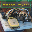
Introduction: How to Test Any Electrical Component! Assembling the Kit, for Dummies


The "TransistorTester with AVR microcontroller" is an incredible little device that will help you figure out the specs of virtually any kind of electronic part. No worries if the labels are scratched off or painted over, just plug it in and test it out! The detailed manual can be found here (updated 26 May 2017, as of this post). I've included it below in the references, along with may other helpful things.
This Instructable explains the HackerBoxes 0018 Circuit Circus instructable, but play-by-play, and for the absolute beginner. I included as much detail as I could find. This kit can be bought at their website, but they have a limited amount. **(edit 24 Sep 2017: I ordered and received this kit: 2017 DIY kits ATMEAG328 M328 Transistor Tester LCR Diode Capacitance ESR meter PWM Square wave Frequency Signal Generator - at 17 USD$, which is is a very good deal; it took two weeks to get here, and also came with a case! Ithad no instructions or parts list, but it has all the right pieces. As I build it out, i'll supplement and update this Instructable with updated / more helpful pictures. I'm actually using this Instructable to assemble it, step by step.)
The purpose of this Instructable is to document every tiny detail so that the absolute beginner would be able to complete this project. I also want to provide practical tips and information, most of which I learned as I did this project.
The companion Instructable will detail how to operate the device and run a few tests.

Step 1: 1.1 the Optional Micro Components

These components were considered optional, so I decided to try it anyways. No harm, no foul, right?
Step 2: 1.2 Use a Sharp Tip on Your Soldering Iron

Step 3: 1.3 Secret to Small Soldering: Teeny Chunks and Tape

Step 4: 1.4 the SVR5-04 SMT Diode Array

*Diagram from this datasheet: http://www.semtech.com/images/datasheet/srv05-4.pdf
Step 5: 1.5 the SMT Capacitor

This is bi-directional, so no worries about which way to orient it.
Step 6: 1.6 the P6KE6V8 Diode (TVS)

*Table found in this datasheet: http://www.jameco.com/Jameco/Products/ProdDS/1541271.pdf
Step 7: 2.1 Checking Your Resistors...

The pictures above should be all you need, just match up the colored stripes, put them in the places it says to on the board!
Checking these yourself is a useful exercise, which you may need to practice for a future project. Either use a multi-meter, or this web-page, to check your resistors: https://www.allaboutcircuits.com/tools/resistor-co...
Once you complete this kit, you won't need to do it again! According to the HackerBoxes Instructable: "There are 24 axial-lead resistors having 12 different values. They all look very similar. We suggest taking a few minutes right now to look up and carefully note their values onto the paper tape attached to the resistors. The resistors are not interchangeable. If each resistor is not placed into its proper location on the PCB, the test device will not function."
Step 8: 2.2 Resistance Is Futile! Adding the Resistors

I added all of them, by type, at once (see above).
Step 9: 2.3 Before Flipping It Over, Ensure You Bend the Wires Slightly, to Keep Them Snug

Step 10: 2.4 Before Flipping Over, Tape the Tops!

Step 11: 2.5 Solder 'n' Snip Snip Snip!

Step 12: 2.6 Finish the Resistor Portion

Step 13: 3.1 Capacitor Installation (no, Not a Flux Capacitor...not Yet Anyways)

Step 14: 3.2 Place Them on Top, Bend, Tape, Solder, Snip!

Step 15: 3.3 the Directional, Electrolytic 'barrel' Capacitors

Step 16: 3.4 Insert, Spread, Tape, Turn, Solder, Snip!

Step 17: 4.1 Transistors, a Crystal, and an LED

*small bit of trivia, on the LED, the negative side (shorter wire) has a barely noticeable flat edge as well.
Step 18: 4.2 Emplacing Pieces Is a Piece of Cake!

Step 19: 5.1 the Chunky Parts: Terminals, Sockets, Power, Etc.

None of these really need to be clipped after soldering, and you should not try to bend them so they stay in the holes -- these parts more than others really need to be taped in while soldering.
Note: The Integrated circuit (not pictured) should not be in the socket as you solder it!
Step 20: 5.2 the Chunky Parts: DIP28 Chip Socket and DIP14 ZIF Socket

Step 21: 5.3 the Chunky Parts: Big Sockets, Tape and Solder!

Step 22: 5.4 Solder the 8 Pin Display Socket

Step 23: 5.5 the 9-Volt Power Cable

Step 24: 5.6 the TFT Color Display (160x120) 16bit

Step 25: 6.1 Finishing Up: Some, Inserting Things, Bolts and Standoff Spacers

Step 26: 6.2 Top Bolts (to Hold the TFT Display)

Step 27: 6.3 Snap in the ATmega328P AVR Microcontroller

Step 28: 6.4 Install the Four Standoffs to the Base

Step 29: 7 Install the TFT Color Display (160x120) 16-bit

Step 30: Turn It ON!

This Instructable has gone on long enough! Here is my companion Instructable to find detailed pictures and instructions on how to operate this device to do some basic testing.
Step 31: References
Another resource from the originator: https://www.mikrocontroller.net/topic/248078#2540547
The HackerBoxes 0018 "Circuit Circus" instructable
The HackerBoxes website where you may be able to order a kit
The ATmega328P microcontroller datasheet complete
Some datasheets for those micro-components
Some alternative sources for this kit (some may need to be translated)
This is a kit with the exact same components -- however with a protective case!2017 DIY kits ATMEAG328 M328 Transistor Tester LCR Diode Capacitance ESR meter PWM Square wave Frequency Signal Generator
There are many out there -- search ebay and other places for "Component tester" "all in one component tester". I wont bother listing anymore particular ones -- they will all be a little different, but with the instructions in this Instructable, you should be able to assemble them.

