
Flying Laptop
The Flying Laptop is a 120-Kilogram micro satellite developed at the Institute of Space Systems (IRS) at the University of Stuttgart, Germany to demonstrate and qualify new small satellite technologies and complete Earth remote sensing tasks with a multispectral imager while an AIS terminal collects ship tracking data on a global scale.
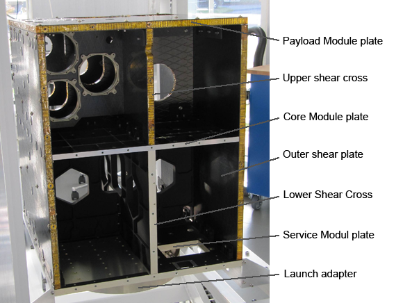
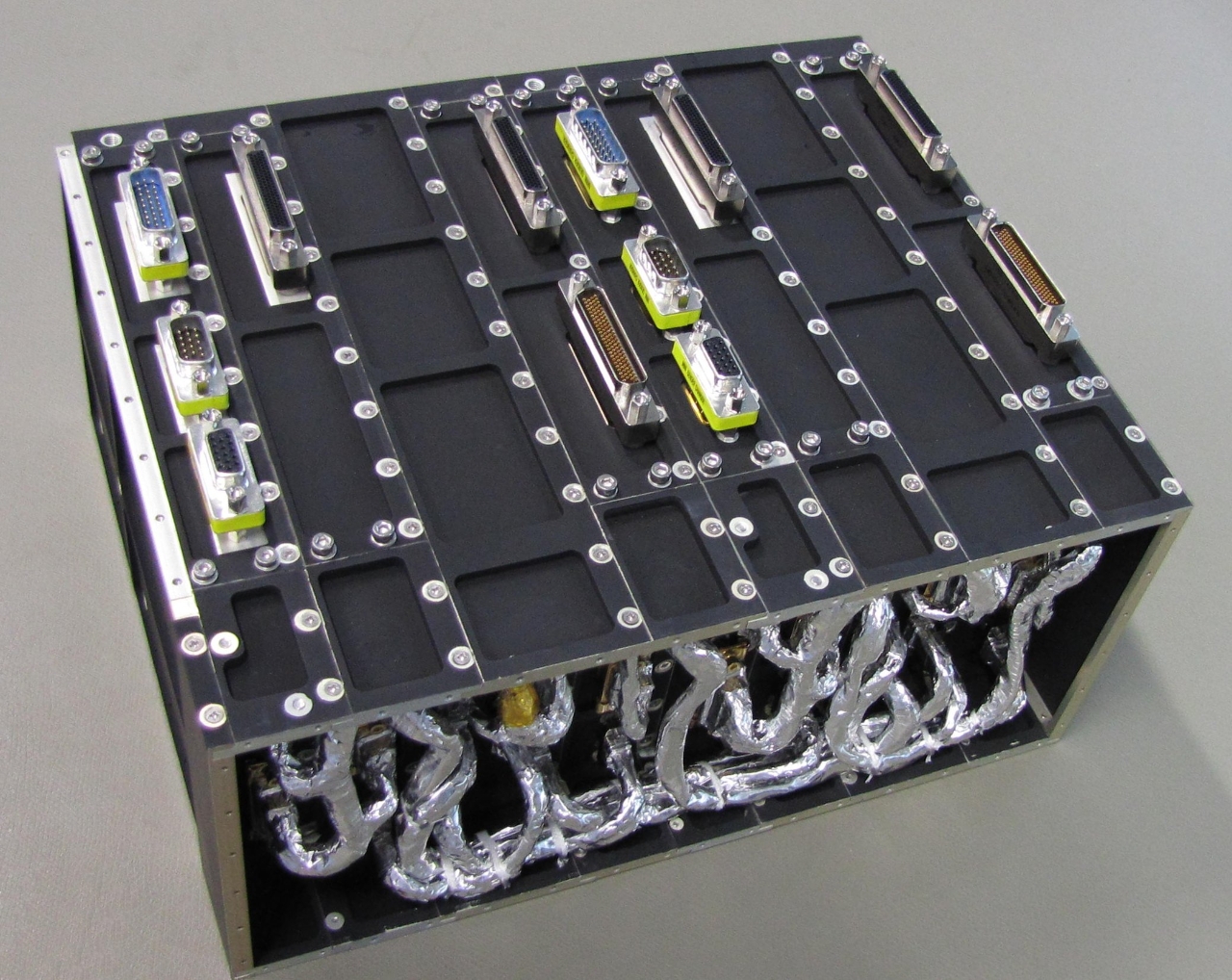
The box-shaped spacecraft is 60 x 70 x 90 centimeters in size and hosts three solar panels, one rigid, body-mounted panel and two deployable panels that are stowed against the satellite side panels during launch. Flying Laptop uses a shelved architecture that allows for easy access to the internal satellite components and enables simultaneous integration.
A two-tier system is employed in which the lower part consists of an aluminum structure that provides structural stability and is cost effective while the upper part hosting the optical components employs a carbon-fiber reinforced sandwich structure that offers low thermal expansion to keep the optics in alignment.
The Flying Laptop design philosophy is one-failure tolerant in all satellite subsystems to create a robust system capable of extended operation in space. COTS (Commercial Off the Shelf) products are used wherever possible on the spacecraft.
Flying Laptop features three solar panels, two of which deploy from the craft’s side panels to form a large power-generation surface of around one square meter. Using triple-junction Gallium-Arsenide solar cells with a 25.3% efficiency, Flying Laptop achieves a maximum power generation of 269 Watts. In addition, the satellite tests out a next-generation 3G triple junction solar cell that is just 100µm in thickness to retire risks for future satellite missions relying on ultra-thin solar cell technology.
Power from the arrays is routed to three off-the-shelf Lithium iron phosphate batteries with a capacity of 35 Amp-hours and a nominal operating voltage of 23.1V.
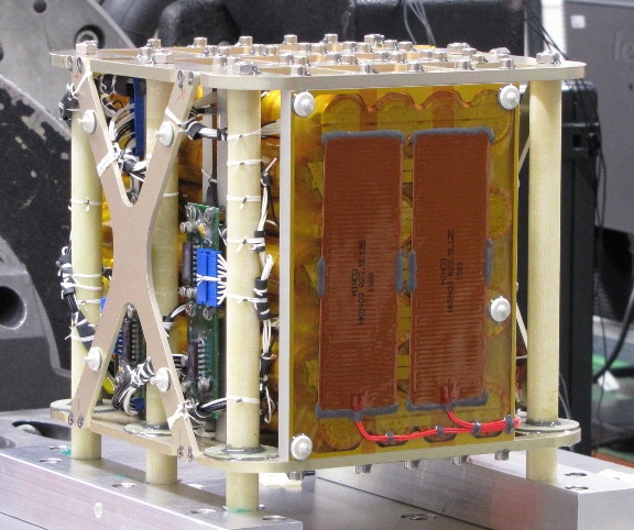
Each battery is connected to one of the craft’s solar arrays: the two batteries fed from the deployable arrays comprise seven strings of five cells for a total capacity of 12.5Ah and a voltage between 19 and 25V while the battery for the central array only has four parallel cells, reducing capacity to 10Ah. This is due to the smaller physical size of the array and its higher operating temperature, being directly coupled to the satellite body. The entire battery assembly is 21 x 20 x 20 centimeters in size and weighs 10 Kilograms.
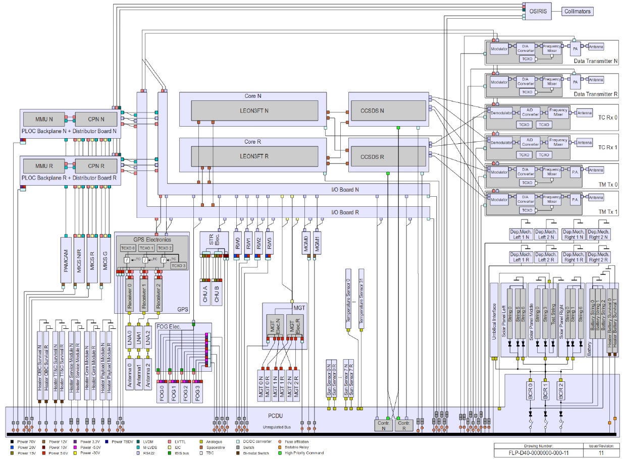
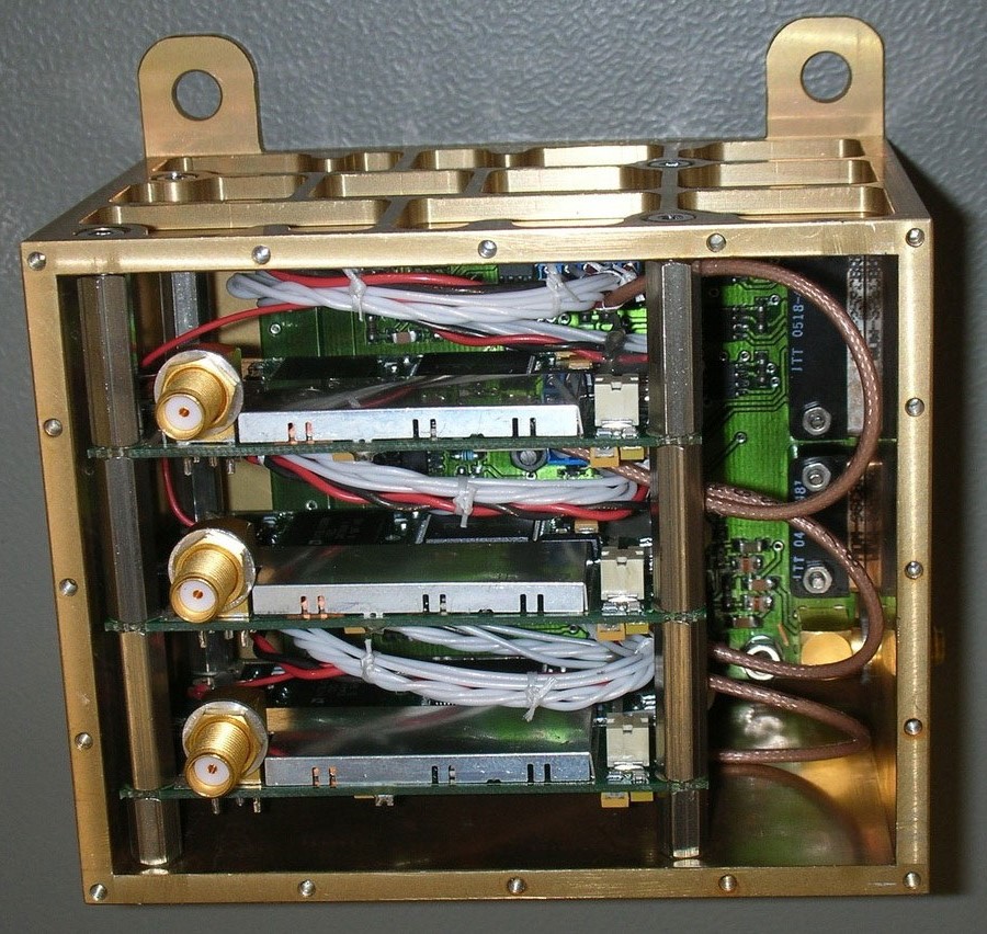
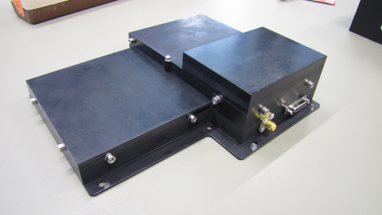
The central element of the power system is the PCDU (Power Control and Distribution Unit), tasked with providing battery charge control and overcharge protection. It also delivers regulated power buses to all satellite subsystems and serves as a critical part of the satellite command & control system, possessing the ability of reconfiguring all onboard computer system units for fault recovery and it also cross checks all commands sent from the central computer and vice versa, allowing the two units to check on each other to ensure full functionality. Housekeeping data collected at the PCDU level is polled by the onboard computer ten times per second using a Common Command – if the PCDU is not polled as specified, a fault flag for the OBC will be raised.
Physically, the PCDU is 22 x 16 x 12 centimeters in size and weighs over 4 Kilograms. Inside are five frame stacks, each with its own printed circuit board using radiation hardened technology tolerant for an accumulated dose of at least 20krad which should enable an operational life of over two years.
The PCDU has two central processing units that operate in a hot backup mode with one in a primary function while the other monitors and can be switched into primary mode the moment the operating CPU is not responding anymore (based on a regular confirmation signal sent from the primary to the backup unit).
The Flying Laptop uses a three-axis stabilized attitude control system with high pointing accuracy and agile maneuvering for the imaging mission. Attitude determination is provided by an autonomous star tracker, three-axis magnetometer, eight coarse sun sensors, inertial sensors and GPS receivers while attitude actuation employs reaction wheels and magnetic torque rods. The ADCS system achieves a pointing knowledge of +/-7 arcsec and a pointing accuracy of +/-150 arcsec.
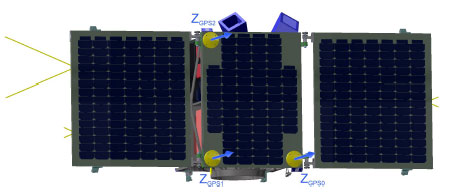
Flying Laptop hosts an experimental GPS system known as GENIUS (GPS Enhanced NavIgation system for the University of Stuttgart micro-satellite). GENIUS uses three GPS antennas arranged in L-shape configuration on the central, body-mounted solar array to deliver real time position with ten-meter accuracy, velocity accurate to 0.1m/s and timing with 1µs accuracy. Additionally, the arrangement of the three antennas, spaced at 44 and 61 centimeters, enables an experimental attitude determination algorithm to be run using the phase and Doppler shift of the GPS carrier signal.
The primary attitude sensor is the µASC (micro Advanced Stellar Compass) developed by the University of Denmark and flown on various missions prior to Flying Laptop. µASC comprises a pair of camera heads and a data processing unit, collecting imagery of the star-filled sky that is compared to an onboard catalog of bright stars from which the precise three-axis orientation in space can be calculated. The µASC on Flying Laptop provides a pointing knowledge of 2arcsec and supports slew rates of up to 10 degrees per second for rapid repointing of the platform.
The magnetometer unit used by Flying Laptop is an Anisotropic-Magneto-Resistive Magnetometer to provide information on the magnetic field vector and field strength for actuation of the toque rods; the Fiber Optic Gyro assembly comprises four single-axis optic rate gyros to provide body rate data. The sun sensors (6° pointing accuracy) are employed in case of a satellite safe mode to ensure proper power generation via solar-pointing of the arrays.
The primary Onboard Computer on the Flying Laptop is a flight-proven design with a LEON3 processing unit operating at a 33MHz clock speed. The OBC is in charge of accepting commands from the ground, actuating all satellite subsystems, accepting housekeeping telemetry and handling data collected by the payloads. Internal satellite communications are accomplished with a 10Mbit/s SpaceWire bus and the Payload I/O board has four dedicated links, one for each major payload component.
The satellite hosts an S-Band communications system with low- and high-gain antennas to achieve the data speeds needed for science data downlink via the high-gain link that requires precise three-axis control due to the antenna boresight. Command uplink is completed at 2.068 GHz, telemetry is downlinked at 2.245 GHz and science data downlink utilizes the 2.425 GHz frequency. The Data Downlink System employed by the payload achieves a data rate of 10Mbps using QPSK modulation.
A special feature of Flying Laptop is a direct connection between the communications board and the PCDU to allow the power unit to receive priority commands, e.g. in case a computer re-set is required.
The Flying Laptop hosts four payload components: MICS – the Multispectral Imaging Camera System, AIS – the Automatic Identification System receiver, OSIRIS – the Optical high-Speed Infrared Link System, and a dedicated Payload Computer.
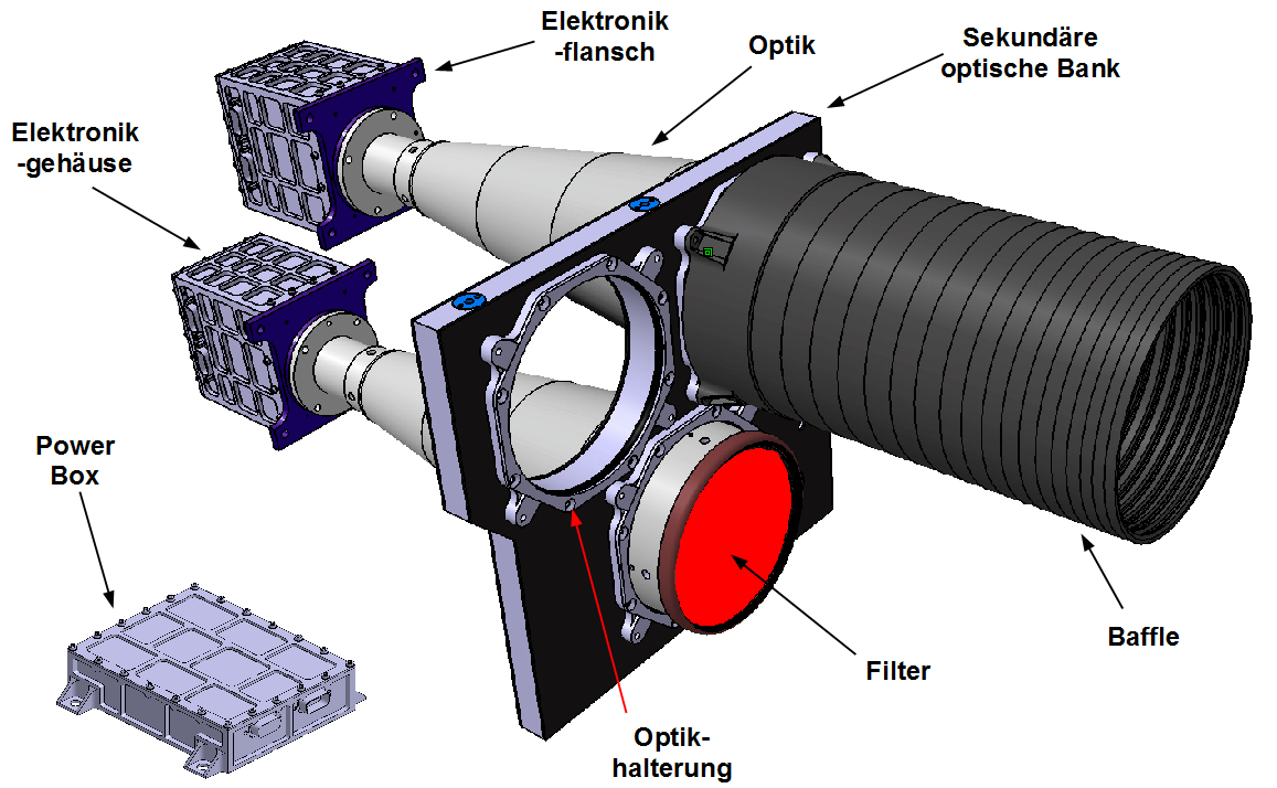
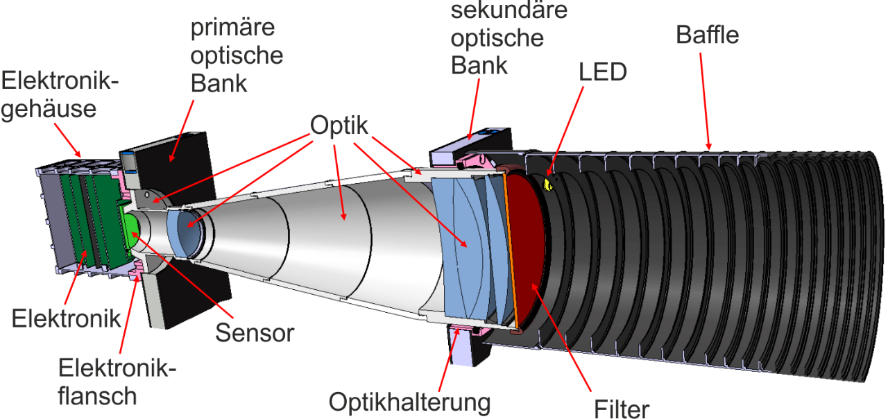
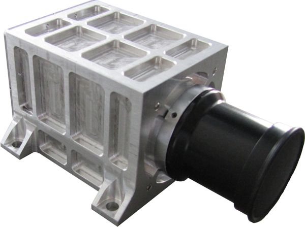
The Multispectral Imaging Camera System (MICS) comprises three single cameras with CCD array detectors for snapshot observation in the visible and near infrared range. MICS is 10 x 9 x 10 centimeters in size and weighs around four Kilograms; the optical system employs identical double Gauss telescopes with interference filters placed in front of the system to set the wavelength passband. The instrument achieves a 21.5-meter ground resolution across a 22-Kilometer swath and covers three spectral channels – 530-580nm (green), 620-670nm (red) and 820-870nm (near infrared).
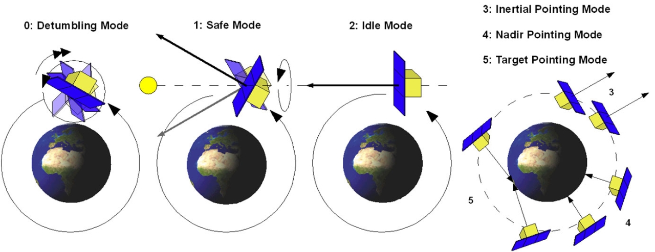
MICS works in close cooperation with the satellite’s attitude control system to establish three different modes of image acquisition. In Inertial Pointing, the star tracker delivers high-precision attitude knowledge and the satellite will remain inertially stabilized for stellar and lunar observations. Nadir Pointing Mode aligns the z-vector of the satellite perpendicular to the Earth’s surface, keeping the cameras pointing directly downward as the satellite makes its orbit, allowing for Earth imaging. A dedicated Spotlight Mode points the spacecraft at a fixed target on Earth, slewing the satellite to compensate for its orbital motion to keep pointing to the target to achieve the required coverage/resolution of the planned scientific observations.
The spotlight mode will be used to capture images of the same target at different observation angles for the measurement of the Bidirectional Reflectance Distribution Function (BRDF) – a fundamental radiometric parameter that is dependent on the vectors of solar incidence, outgoing reflection and surface normal as well as the properties of the surface itself.
This measurement is of relevance for the correction of in-situ or satellite measurements of Earth’s surface and needs to be taken into account in order to standardize collected data from different sensors to make them comparable with each other. BRDF correction is typically completed using algorithms that are based on measurements conducted on different surfaces and SBR is expected to add spaceborne data for the refinement of correction models.
An auxiliary instrument to MICS is a Panoramic Camera for the collection of context color video of Earth. The entire camera unit weighs 400 grams and measures 12.6 x 7.8 x 5.8 centimeters in size, employing 25mm optics and a COTS camera with a 1280 x 1024 CMOS sensor, creating a field of view of 20 x 16 degrees which in turn corresponds to a 200km ground swath. PanCam achieves a 160 meter ground resolution.

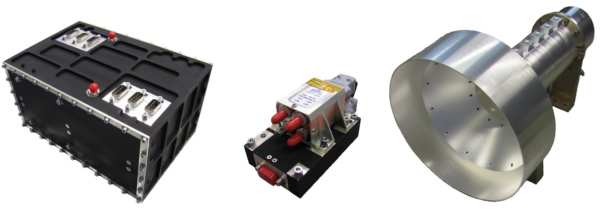
The Flying Laptop is also carrying a laser communications payload known as OSIRIS – Optical HighSpeed Infrared Link System. OSIRIS was developed by the German Aerospace Center to realize a laser communications terminal enabling high-data rate downlink communications for small satellite missions – opening possibilities for data-intensive payloads on small satellites which may currently rely on large satellite platforms and their communications capability.
OSIRIS comprises two optical transmitter units integrated in a single housing. Each unit consists of a laser source, modulators and optical fibers that connect the source to the collimator units installed on the satellite’s optical bench. One laser source employs a high power laser diode while the other uses an erbium doped fiber amplifier (EDFA). Both operate in the infrared band, at a wavelength of 1550 nanometers and OSIRIS is expected to reach a data rate of 100Mbit/s. All in all, OSIRIS weighs around 1.5 Kilograms and requires 25 Watts of power during operation.
The second primary payload of the Flying Laptop is a receiver for the Automatic Identification System, developed at DLR Bremen. The Automatic Identification System is used by sea vessels that send and receive VHF messages containing identification, position, course and speed information to allow the monitoring of vessel movements and collision avoidance as well as alerting in the event of sudden speed changes.
These signals can be transmitted from ship-to-ship and ship-to-shore to allow the monitoring of a local area, but deploying space-based AIS terminals allows a broad coverage and data relay to ground stations for monitoring of large sea areas. However, due to the large footprint of satellites, overlapping and signal collisions become a problem, especially for frequented traffic routes, requiring a steady improvement in reception technology to separate the different signals.
The AIS Receiver was a late addition to the Flying Laptop and will be employed in conjunction with the satellite’s cameras to examine the accuracy of the position data transmitted by ships.
The Flying Laptop Payload Suite is controlled by a dedicated PLOC computer unit based on Field Programmable Gate Array technology coupled with three 128MB DDR3 RAM, 18MB of SSRAM and a Mass Memory Unit with 2GB Flash to hold the payload data.