Introduction: Alarm Clock Using the RTC of the Arduino 101


This is a fully functioning digital alarm clock with a stop and snooze button, as well as a display for the current time and date. It uses the built in Real-Time-Clock (RTC) of the Arduino 101 board for displaying the current date and time, as initialized by the user. The alarm time is also specified be by the user by inputting the date and time that he/she would like to be woken up. In addition, it is designed to be versatile, especially for those night owls who have trouble waking up in the morning, where the buzzer frequency and interval can be adjusted, as well as an adjustablesnooze time.
I was motivated to make this project since I've always had trouble waking up in the morning even with 3 separate alarm clocks!
Step 1: Tools and Materials

- Arduino 101
- 2 half+ breadboards
- Buzzer
- LED
- 2 pieces of push button switches
- 2 pieces of 10kΩ resistors
- 100Ω resistor
- Potentiometer
- LCD Display
- A lot of jumper wires
Step 2: Wiring the LCD


The LCD is used to display the current time and date just like any traditional digital alarm clocks. The entire LCD display will take up one of the half+ breadboard.
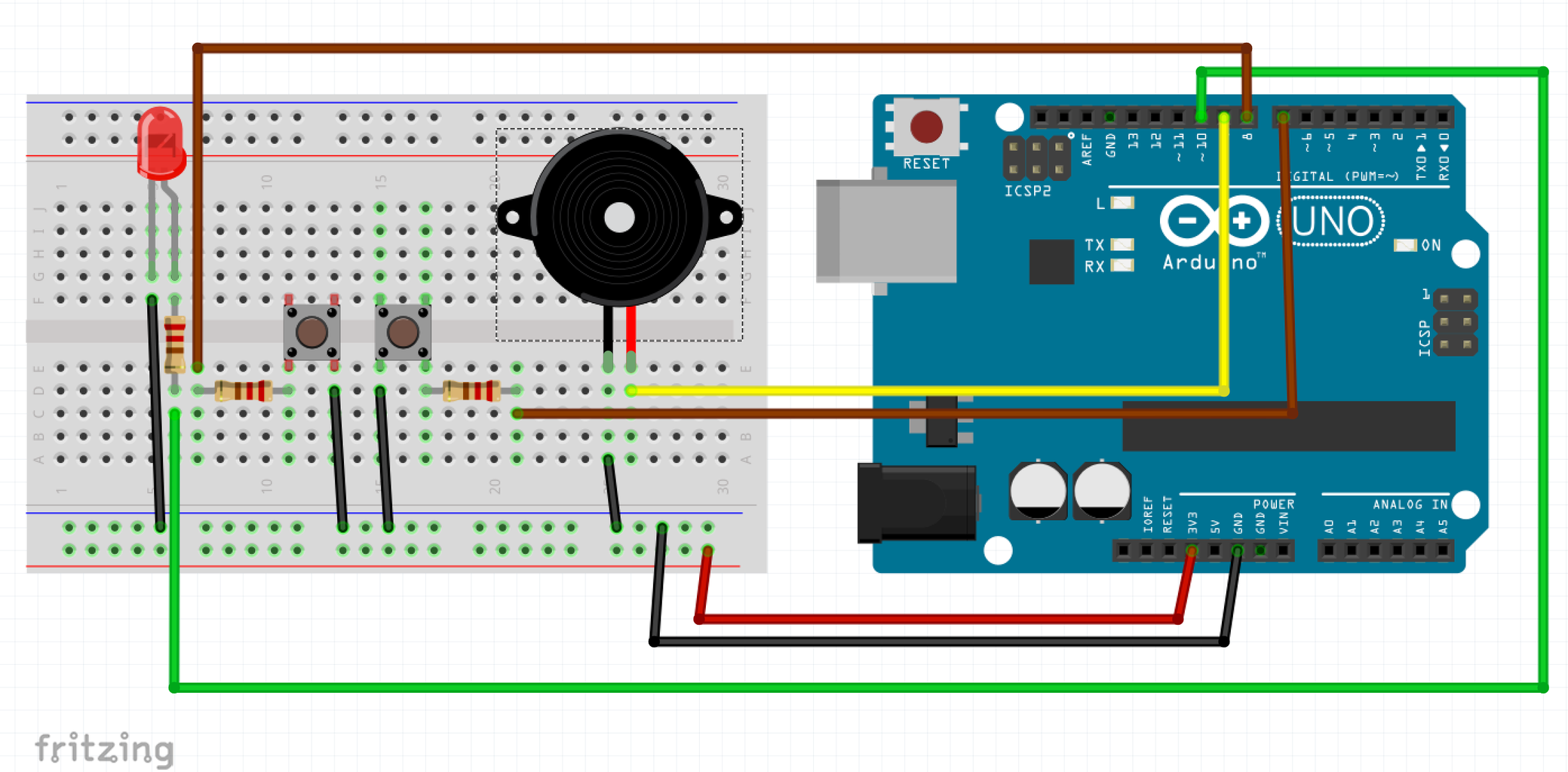
Please note, It is more straightforward to follow the schematic for the LCD screen, but the following order of connections helps keep the wiring process more orderly. Since many jumper wires are needed, to keep the wires orderly, I chose to represent ground wires as black or white coloured jumper wires and 3.3V wires as red or orange wires in the circuit.
- Connect the breadboard's 3.3V power rail to the LCD screen's pins 2 and 15
- Connect the breadboard's ground rail to the LCD screen's pins 1 and 16.
- Connect the the LCD screen's pin 4 to the middle pin of the potentiometer.
- Connect one of the outer pins of the potentiometer to the red power rail, while the other outer potentiometer pin will be connected to the ground rail of the breadboard.
- Connect the Arduino digital signal pins 2 to 5 to the LCD screen's pins 14 to 11, in their respective consecutive order.
- Lastly, connect the LCD screen's pins 4 and 6 to the Arduino digital signal pins 11 and 12.
Step 3: Wiring the Alarm System


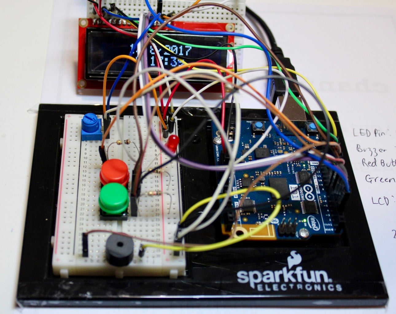
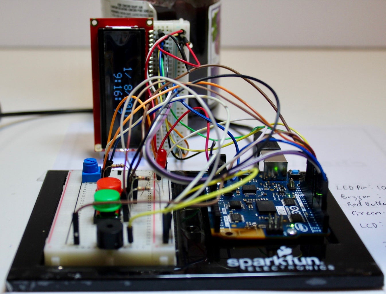
The alarm system will be wired on another half+ breadboard to keep the wires orderly, as the first breadboard is already crammed. The red button is the "Stop Alarm" button. While, the green button is the "Snooze" button. Since, both are push button, they are active low, meaning that they would produce a digital low or 0 when pushed.
- Place all the remaining components (LED, two push buttons, and buzzer) on non-connected breadboard holes.
Connecting the Buzzer
- Connect one of the buzzer pins to pin 9 on the Arduino Board.
- Connect the remaining buzzer pin to the ground rail on the breadboard.
Connecting the LED
- Connect the LED's anode to a 100Ω resistor in series to pin 10 on the Arduino board.
- Connect the LED's cathode to the groundrail not he breadboard.
Connecting the Push Button Switches
- Connect one of the pins of each of the switches to a 10kΩ resistor in series to the red power rail not he breadboard, respectively.
- Connect the remaining pins of both the switches to the common ground rail on the breadboard.
- Connect the each of the switch's pin connected to the 10kΩ resistor to pins 7 and 8 on the Arduino, which are shown as the brown jumper wire in the images.
Piggybacking the Power Source
- Connect the 3.3V power from the Arduino 101 board and connect it to the red, positive power rail on the first breadboard.
- Connect the GND from he Arduino 101 board to the black rail on the first breadboard.
- Connect the red and black power rails from the first breadboard to the red and black power rails of the second breadboard, respectively, to distribute the power in parallel.
Step 4: Coding


Set the time and date you want to be woken up using the variables month1, day1, year1, hour1, minute1, and second1. You may also optionally set the frequency of the alarm (buzzerFrequency), snooze time (snoozeTime), and the intervals between alarm/LED beeps or blink (buzzerInterval).
//include the CurieTime Library
#include <CurieTime.h>
#include <LiquidCrystal.h>
int ledPin = 10;
int buzzerPin = 9;
int snooze = 7;
int stopAlarm = 8;
int snoozeTime = 60000 /// 1 minute
int buzzerFrequency = 1000
int buzzerInterval = 100;
//instantiate the lcd
LiquidCrystal lcd(12, 11, 5, 4, 3, 2);
void setup()
{
  pinMode (9, OUTPUT);
  pinMode (10, OUTPUT);
  pinMode(8, INPUT);
  pinMode (7, INPUT);

  //start lcd at 16 x 2
  lcd.begin(16, 2);
//clear the lcd lcd.clear();
  //set time to Today: August 1, 2017. 9:16 PM Please change to your time / date
  setTime(9, 16, 00, 8, 1, 2017);
  Serial.begin(9600);
   tone(buzzerPin, 1000);
   delay(100);
   noTone(buzzerPin);
  long month1 = month();
  long day1 = day();
  long year1 = year();
  long hour1 = hour() + 8.0; // 8 hours from now
  long minute1 = minute();
  long second1 = second();
}
void loop()
{

  if (month() == month1){
    Serial.println("hello");
  }
  if (month() == month1 && day() == day1 && year() == year1 && hour() == hour1 && minute() == minute1 && second() == second1){
    Serial.println("Hello WOrld");
    for (int i = 0; i<60/(buzzerInterval/1000); i++)
    {
      digitalWrite (ledPin, HIGH);
      tone(buzzerPin, buzzerFrequency);
      delay(buzzerInterval);
      noTone(buzzerPin);
      delay(buzzerInterval);
      tone(buzzerPin, buzzerFrequency);
      delay(buzzerInterval);
      noTone(buzzerPin);
      digitalWrite (ledPin, LOW);
      delay(buzzerInterval);
      if (digitalRead(stopAlarm) ==0){
        noTone(buzzerPin);
        break;
      }
      if (digitalRead(snooze) ==0){
        noTone(buzzerPin);
        delay(snoozeTime);
      }
    }
  }

 //create a character array of 16 characters for the time
 char clockTime[16];
 //use sprintf to create a time string of the hour, minte and seconds
 sprintf(clockTime, "    %2d:%2d:%2d    ", hour(), minute(), second());
//create a character array of 15 characters for the date char dateTime[16]; //use sprintf to create a date string from month, day and year sprintf(dateTime, " %2d/%2d/%4d ", month(), day(), year());
 //set cursor to column 0, row 0
 lcd.setCursor(0, 0);
 //print the date string over lcd
 lcd.print(dateTime);
 //set cursor to column 0, row 1
 lcd.setCursor(0, 1);
 //print the time string over lcd
 lcd.print(clockTime);
}
Attachments

Step 5: Alarm Demonstration
Note: The demonstration video was cut short such that there's no waiting involved before the alarm rings, since that would be quite a boring video to watch.

Participated in the
Makerspace Contest 2017

Participated in the
MacGyver Challenge