

Introduction: Arduino Controlled Sound Responsive LED Display


The aim of the project was to produce a colourful sound responsive LED display. It serves no purpose other than decorative but does look very nice and can add to the atmosphere in a room where music is playing. It is also a fun electronics project with which to learn more about arduino programming and electronics. It cycles through different sound reactive light patterns when a button is pushed. Some of the patterns contain multiple sub patterns.
The project uses modern WS2812 addressable LEDs to produce the lighting effects. These LEDs consist of a red, green and blue LED on one chip combined with a tiny micro controller that takes a signal in and sets the brightness of all 3 colours using an 8 bit value for each channel. They update at high speeds to produce colour mixing effects and even animations. They use 3 wires; 5 volts, ground and a signal wire.
An arduino micro controller generates the signal. An arduino is a simple, cheap and slow 8 bit computer that can run software to generate a signal to control WS2812 LEDs. It maxes out at 512 LEDs which is enough to produce good results.
The arduino runs code that allows it to take an input from a MAX9814 auto gain microphone. This microphone works particularly well with the arduino compared to most cheaper microphones and is what allows the LEDs to respond to sound.
Apart from these basic components there is a power supply, a button to change modes, a couple of resistors, some nuts and bolts and miscellaneous wires and connectors. The case was 3D printed using translucent PLA.
Step 1:
Step 2: Parts List and Overview


A google documents spreadsheet of the parts required can be found here;
https://docs.google.com/spreadsheets/d/1f6vPkE1BGE...
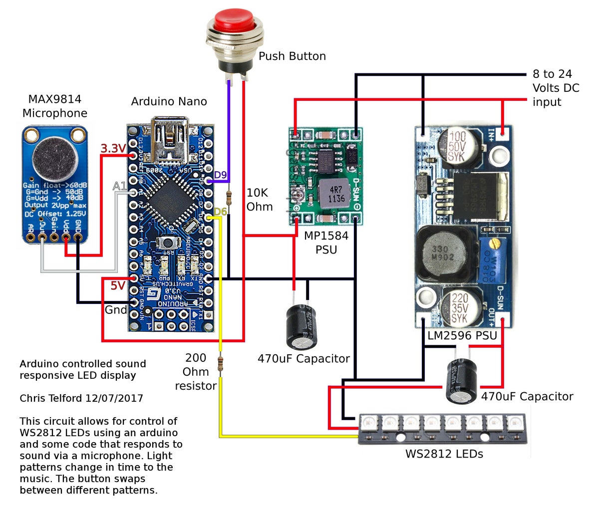
The control circuitry consists of an arduino with a MAX9814 microphone and a button, hooked up to a switching power supply and some WS2812 LEDs. There is a second switching power supply for the LEDs as these are higher current devices than the arduino and microphone and doing this can help separate the arduino from any noise generated by the LEDs. The grounds on both power supplies should be common and it's worth putting some 470uf electrolytic capacitors across each power supply to add extra power filtering. The circuit could be built with one power supply and no extra capacitors and it would probably be fine.
The whole circuit is powered by a 7 to 26 volt DC power supply. The voltage range is large because of the use of switching power supplies internally. I suggest using a suitable battery or a 12 volt mains adapter that can provide at least an amp to power everything.
There are two resistors on the circuit board. A 10k Ohm resistor for the arduino and the button and a 200 ohm resistor inline with the WS2812 data pin to add some extra power protection.
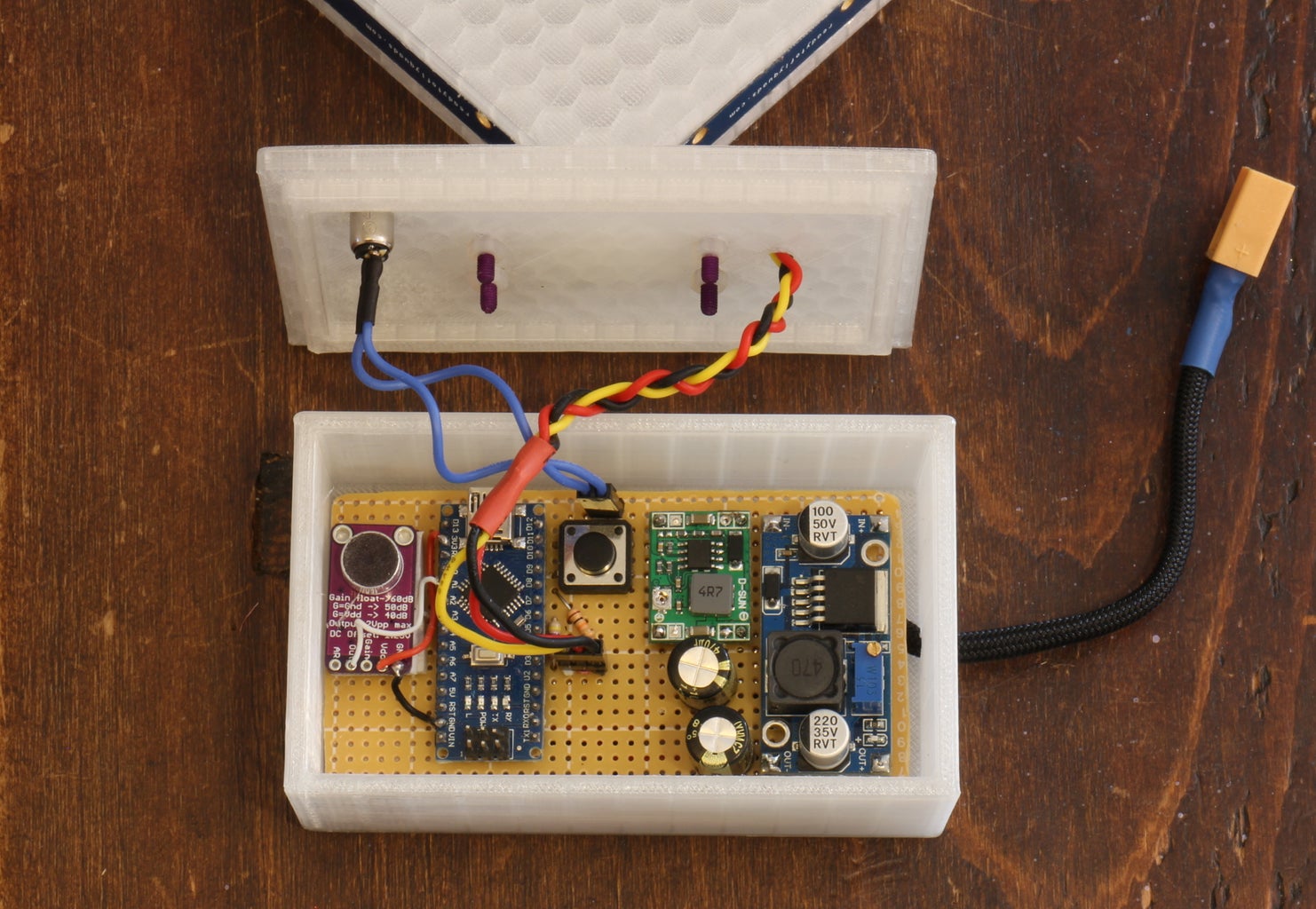
Use pins and connectors to plug the external LEDs and button into the circuit board in a convenient fashion and another connector for the main power input. I suggest using whatever style of connectors you like best. In the pictured example there are two monentary buttons, one on the circuit board for testing and a second external one for after the project was completed. Both do the same thing and you only need to use one.
I used WS2812 LEDs that came as strips of 8 on short lengths of PCB material. I used 4 strips for 32 LEDs in total. Arranging them around the sides of a square produced good results.
Step 3: Pins and Wiring


General Advice
Lay the components out on some perforated copper cladded circuit board with enough space between everything to add the power and signal connections. Use the pictures of mine as a guide if it helps but there is no need to copy them exactly; just make sure all the connections get to the right pins and it will work.
I used the box I put my circuit in as the base for the light itself so there was no need to build it as small as possible. I made an effort to solder the higher current connections onto the reverse of the perf board to keep things safe and neat and used thin wires to wire up the expensive microphone on the front of the circuit so that I could easily remove that in the future if necessary.
Arduino
The arduino is connected to the microphone, the button, the LEDs and the 5v MP1584 power supply.
The microphone solders to the arduino's ground pin, 3.3v pin and Analogue 1 pin via it's ground pin, Vdc pin and Out pin respectively.
The button is soldered to the arduino's 5 volt pin and Digital pin 9. Digital Pin 9 should also be connected to ground via a 10K ohm resistor. The arduino 'button' tutorial explains this in detail; https://www.arduino.cc/en/Tutorial/Button
The LED data pin is soldered to Digital pin 6 on the arduino with a 200 Ohm resistor inline between the arduino and the LEDs.
Arduino Power supply
The arduino's 5 volt and ground pins should be wired to the adjustable MP1584 voltage regulator ONLY after it has been set to 5 volts output. This power supply will only power the arduino and the microphone. I have used the 3.3 volt regulator on the arduino to power the microphone which works on 3.3 volts or 5. Any small switching regulator could be used here, I just happened to have n MP1584.
LED Power supply
The LM2596 voltage regulator is rated at 10 watts which is enough to power the LEDs. This should be set to 5 volts output then wired to the 5 volts and ground pins on the WS2812 pins. Grounds should be common on both power supplies but the 5 volts for the arduino and LEDs should be kept seperate. Other similarly rated switching power supplies should work but the LM2596 is cheap and plentiful on ebay.
Main Power Supply
You could use any mains to 12 volt power supply capable of providing 1 amp. Alternatively use an 8 to 24 volt battery. This should power both switching regulators described above.
Step 4: Case and LED Diffuser


Any project box case of about the right size could be used. I 3D printed a case with holes in the right place for my circuit board inputs and outputs.
The LEDs themselves need some kind of diffuser to look good. I 3D printed a square from translucent PLA with slots around the outside to fit the LEDs in. I used a hexagonal fill which added some texture to the inside of the square to help defuse the light and add a nice hexagonal effect. The diffuser doesn't have to be 3D printed, anything with the right light transmitting properties would work.
I used M3 nuts and bolts to connect the diffuser to the case.
My design can be found at;
Step 5: Code
Once the circuit is done you can flash the code to the arduino. The code I used can be found on here;
https://gist.github.com/c5f3db43a4230ad698fafcc134...
It is an unoriginal combination of various different FastLED and Adafruit Neopixel demo codes designed to be used with the MAX9814. This is software does not belong to me.
The code has been hacked together and probably isn't very good. It just about works. If anyone can do a better job please let me know, I'd love to see what you come up with.
If you are unsure about flashing code to an arduino then please see the arduino website;
You will need to download the arduino client software from their website to open the code I have provided. This software uploads the code to the arduino.
Attachments

Step 6: Job Done
Once you've flashed the code to the arduino you should unplug it from USB then power the whole device up off your mains adapter or battery. After a second or two it should light up. Play some music to see the effects respond to sound. The button will swap between different modes but sometimes needs to be pressed down for half a second or so before it responds.
Fit the electronics inside the printed box and then used some M3 nuts and bolts to attach the square display section to the lid. The LEDs can be glued into the slots in the side of the square display section using a transparent glue like 'Uhu all purpose adhesive' or similar. Thin super glues are more likely to make a mess and should be avoided.
Step 7: Taking It Further
I went with a simple square for my defuser as the LEDs I had were mounted on PCBs and couldn't be bent into curves. WS2812 LEDs are available as tape, individual LEDs, strings of LEDs and more. The same code and electronics I used could be made to drive different arrangements of LEDs that would give different effects. I would encourage other people to try different ways of doing this. Please send me pictures if you make something cool.


