

Introduction: RFID Door Lock


This instructable was created in fulfillment of the project requirement of the Makecourse at the University of South Florida (www.makecourse.com). The goal of this project is to develop the prototype for an RFID door lock. An RFID consists of a scanner and a card. When the card is placed on the scanner an action usually takes place. In this case it will be turning a motor to unlock the door.
Step 1: Parts Needed


1. Access to a 3D printer to print out the dead bolt mechanism
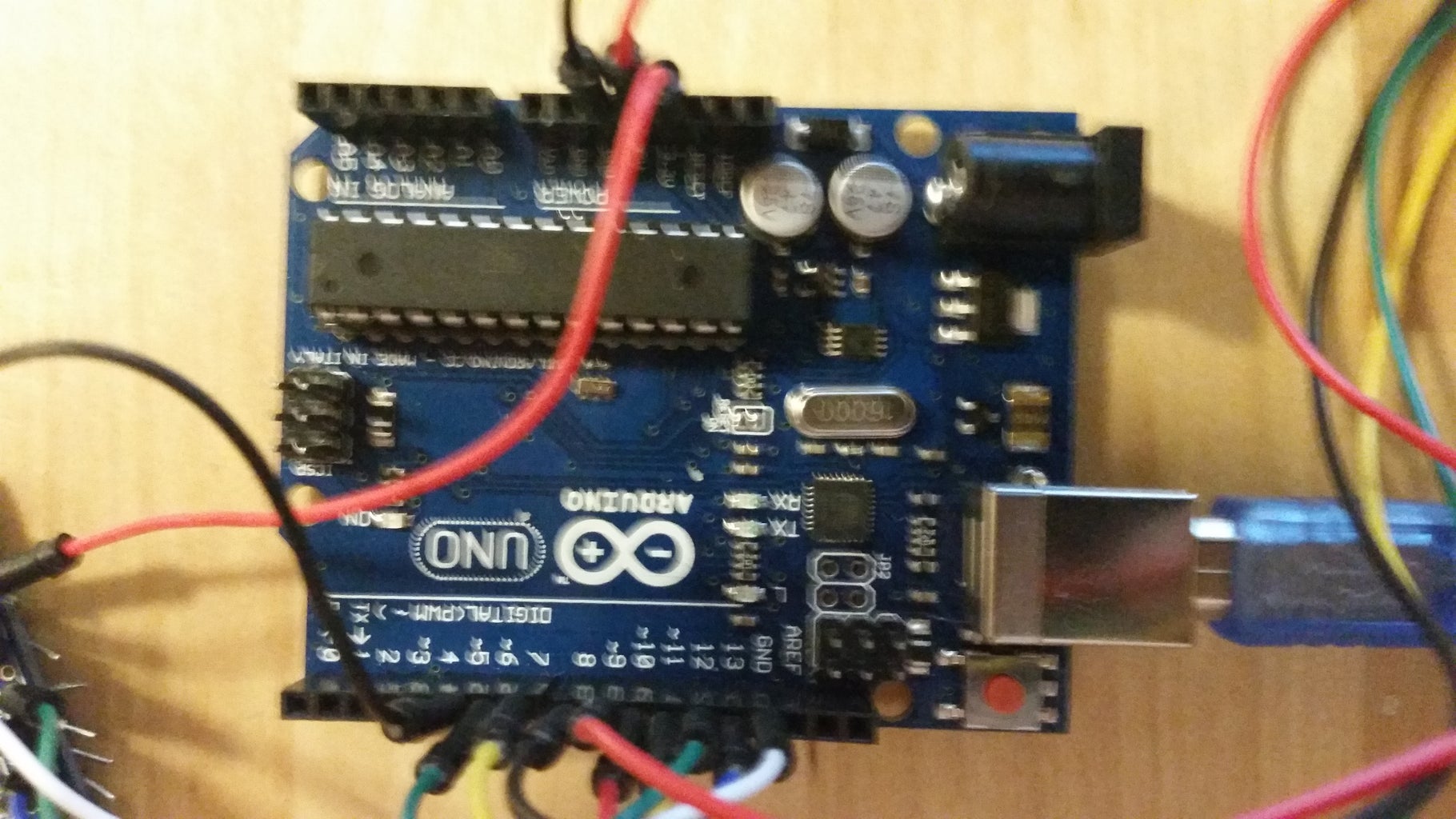
2. Arduino - as shown in the picture, it will be used as the building block for the code
3. Stepper Motor system - includes the Stepper motor in the attached manual, with a Stepper motor driver as shown.
4. RFID system - consists of the RFID scanner and the RFID card shown in the picture. The manual is attached as well
5. Black box - used to house the electronics, but any box will do that can hold up
6. Door handle - can be any door handle really as long as it works!
7. Door - If you want to implement this into a door, you will need a door to do it on. I did a wood cutout of a door for simplicity of presentations
8. Jumper wires - several different jumper wires will be needed to connect all of the pieces
9. Drill - used for the screws and cut out any needed holes
10. 9V Battery - powers the system with a snap connector laying on a battery holder
11. Switch - used to save the battery when not being used
12. Screws, washers, and nuts - a set of 4 to hold the rack in place, a set of 4 to hold the Arduino in place, a set of 4 to hold the Stepper motor driver in place, a set of 4 to hold the RFID scanner in place, a set of 4 to hold the black box on the door, and a set of 2 long to hold the stepper motor in place

Step 2: 3D Modeling


The project was modeled in Solidworks before further actions were taken to ensure everything would fit and review possible mounting locations. The final solidworks assembly with all of the parts is attached as a zip file. The pictures show the final product and the basic contents of the black box. This step gives you a good idea of what the project will entail and it is a good idea to review the model to ensure you know what will be going on in the rest of the steps.
Attachments

Step 3: 3D Printing

Rack and Pinion system
I was able to 3D print them using the attached solidworks files and STL files named Pinion, rack flat, and rack. This will comprise the pinion to go on the stepper motor, the rack to simulate the dead bolt, and the bars around it to keep it in place. Grey PLA plastic was used, but other plastic would work fine with it. The bars can be substituted for something else like wood rods instead of 3D printing them.
Step 4: Control System


The control system for the project is shown in the block diagram. It starts with the RFID scanner. Once the RFID scanner finds a RFID card that matches up to it, it sends a signal to the Arduino. The Arduino then sends power to the stepper motor from the battery, if the switch is on, to tell it to move to simulate the door unlocking and locking. The breadboard setup is shown along with the schematic and Fritzing model. The stepper motor is wired through the driver to the Arduino. The RFID scanner is wired to the Arduino as well. The power is given by a 9V battery with a switch. The RFID card is programmed into the code so it can be specialized to increase security. If there is no RFID card the system does nothing, but keep the door locked. The Fritzing model can be referred to if there is any problems in setup.
Attachments
Step 5: Setup and Mounting


The inside was mounted as shown in the picture. The rack system with supports was mounted first since it was the longest pieces and pushed toward the end of the box and screwed down in place. From there the stepper motor was mounted to be able to make the rack and pinion touch to move. The Arduino was then mounted sideways to give enough room to plug in the stepper motor system and plug in the battery. The stepper motor drive was mounted on the side so the wires would be up off the bottom of the box. The battery holder was mounted to the far side of the box to give as much room as possible to plug into the Arduino. The RFID was mounted later since it constricts the movement of the lid. A hole was drilled into the lid to be able to put all of the wires through. A hole was also drilled for the switch which was mounted through a nut on the back. The wires were attached as they went and the soldering was done as needed to ensure everything stayed in one place.
Step 6: Arduino Sketch


The project uses an Arduino Uno as the basis for the coding. Connected to the Arduino is the RFID scanner and Stepper motor. The attached code, functions, and needed libraries are used to turn the stepper motor when the RFID card is placed on the scanner. The stepper motor is currently set to unlock the door, wait 3 seconds, and unlock the door. The Stepper motor library is used to call on movements for the stepper motor specifically. The RFID library (MFRC522 in this case) is used to initialize and run the scanner with the card. The functions file is used to store blocks on the card to personalize it and add a security measure.
The code is divided into 3 sections. The first section defines the needed libraries and variables. This is where all the pins are defined, libraries are found, and variables are done. The next section sets up the system. It initializes the SPI, the RFID scanner, and stepper motor to ensure all are ready to perform their own actions for the code. The last sections is the loop where the actions are sent to the system. This is where the loop is defined the make the stepper motor move if a card is identified to simulate the door unlocking and locking. The code is commented and described to show exactly what each line does for the system.
From this the code can be altered some to better fit a certain need or project depending on what you are using this for. For the motor's speed, the gear ratio in the code can be altered to get a different gear ratio from it. In addition to this, the current code has a 3 second time delay in it to open the door,get through the door, and close the door. This was mainly used for presentation purposes. This can be changed to a more appropriate time to get best performance.
Step 7: Finishing Touches

At this point, the black box should have all of the components in it and wired up correctly with a working code. Test it out to ensure the rack and pinion system is working correctly with the stepper motor and RFID systems as shown in the video. Once this is done it is time for the finishing touches and mounting it on the door. Inside the box there is four short places to drill which is where the mounting screws will go for the door. Drill these holes out along with the correct place on the door. For the door itself, the box should go where the deadbolt was. Align the old dead bolt location with the new one and the box should be mounted as such. If the handle is not mounted on the door, do this now as shown in the door handle manual. Once that is done, the project is complete and you have yourself an RFID door lock.
Step 8: Final Product

The final product is shown in the pictures and video. One picture shows the final from the outside while the other shows what it looked like from the inside. The video shows the full working model. The project is able to turn on from the switch, read the RFID card using the scanner, send a signal to the stepper motor, and have the stepper motor turn to unlock the door. A short time later (3 seconds for this case), the stepper motor moves again to move the rack and pinion system and lock the door. The door can then be switched off to save battery life.


