

Introduction: Making a Wooden LED Clock


In this instructable I build a simple wood LED clock, using modern electronics components and traditional wood and metal working techniques.
I use a 16x9 LED matrix from Adafruit as a digital clock face, power it with an Arduino nano and use a DS3231 Real Time Clock (RTC) to keep time. I also show how to make the pretty reclaimed wood and aluminum box as the case. All with simple tools (plus small drill press). This is a fairly simple electronics build, I assume basic knowledge of Arduino and an ability to do some simple soldering. A good getting started Arduino tutorial is https://www.instructables.com/id/BLINK-LED-USING-A... and Instructables has lots of excellent soldering guides.
If you're more interested in electronics then woodworking
It's perfectly possible to make box from MDF, use an electronics project box, laser cut, CnC or 3d print a box and just skip the woodworking parts of this instructable.
If you're more interested in woodworking then electronics:
The electronics for this project are fairly simple. I'd suggest you first get familiar with Arduino by following an Arduino getting started tutorial. If your not interested in electronics you could mount a small analogue clock kit instead or use components from of an off the shelf digital clock.
Safety message
This project involves high speed drills, rotary, metal work and very sharp tools. Always wear safety glasses when drilling or using the rotary tool. Also keep hands away from the sharp edge of chisels, knives and hand planes. Always cut away from yourself. Be careful!
Step 1: Watch the Build Video
I've created a video showing the build process for this project. Hope you enjoy it. Please check out my other build videos and consider subscribing to my channel.
Step 2: Gather the Tools and Materials

For this project you will need:
Electronics
- IS31FL3731 LED i2c driver http://amzn.to/2sBpt6x or https://www.adafruit.com/product/2946
- Warm white 16x9 charlieplexed LED grid https://www.adafruit.com/product/2974
- DS3231 Real Time Clock http://amzn.to/2rSy32Q
- Arduino nano: http://amzn.to/2rSI0gL
- Solderless Breadboard for prototyping: http://amzn.to/2rSIp2O
- Breadboard wires: http://amzn.to/2sBGwoL
- Electronics perf board to use as a drill template http://amzn.to/2rSBHth
- Electrical tape
- Solder and a soldering iron
Wood and metal working
- Sharp chisels and mallet
- Hand plane to clean up the wood
- Small saw
- Hand router
- Finishing oil
- Sand paper
- drill or drill press with 1mm and 4mm bits
- metal file
- rotary tool with cutting wheel and grinding disks
- hacksaw
- hot glue gun
- 5min epoxy
- Utility knife
Materials needed:
- Block of wood to make the case. Mine measured 8.5cm by 6.5cm by 4.5cm.
- 5mm aluminum plate. (Optional)
- 4 small wood screws.
Step 3: Build the Electronics and Upload the Arduino Sketch

Solder the LED's IS31FL3731 breakout board to the LED matrix, Adafruit has very detailed instructions on this here.
Using the above circuit diagram build the circuit using the breadboard. This circuit diagram can also be viewed here.
Install the Arduino sketch
The Arduino sketch can be downloaded here. Download and open it in the Arduino IDE then upload it to the Arduino. If all is working the 16x9 LED should be showing the time. If the time is incorrect follow this instructable to set the correct time on the RTC.
Your now ready to move on with making the box.
Step 4: Preparing the Wood

I used a piece or reclaimed hardwood that ended up measuring 8.5cm by 6.5cm by 4.5cm, including the aluminum bracket. Saw the wood down to the size you want, then clean it up with a sharp hand plane or sand paper. It's now time to drill the grid of holes for the LEDs
Step 5: Drilling the Grid of Holes for the LEDs


I lucked out with this project. An electronics perf board has holes placed exactly where the LEDs are. So choose a spot on the front you want the grid to be. Tape the perf board down and mask out a grid of 16x9 holes.
Now with the drill press and 1mm drill bit, very carefully drill out a grid of holes using the perf board as a template.
Step 6: Saw Off the Back Plate

I sawed off a section of the original wood to use as a back plate. Doing this results in the end grain between the main section of the box and the back plate matching. My back plate width was 1/4inch thick. Using a small saw, saw off this section and clean up the saw marks with the hand plane.
Step 7: Chisel Out the Middle of the Box


Using a ruler and/or marking gauge, mark out the section of the box that is going to be chiseled out. If you don't want to use a chisel, a drill press with a forstner bit or electric router could be used instead.
Carefully chisel out the material to make a hollow box. I left 1/4inch of material on all sides. Clean up the bottom of the inside of the box with a hand router.
Notes about chiseling
Chiseling out this material is the same technique as chiseling out a dado. This a good tutorial for how to cut a dado.
About chisel safety
You could shave with a sharp chisel, hence safety is important. In fact, shaving the back of your hand is a chisel sharpness test! My rule is to always keep your hands behind the blade, never in front.
Step 8: Make the Aluminum Bracket (optional)


If you want to make an aluminum bracket, use 5mm thick aluminum plate and cut it to size with a hacksaw. Aluminum is soft and cuts easily. Using the drill press drill out an internal rectangle as pictured. Then using the rotary tool with a cutting disk cut out the inner rectangle. Clean up the cut marks with a metal file.
Using 5min epoxy, glue the aluminum bracket to the wooden box. Wipe up any excess glue.
Step 9: Finishing the Box

Drill 4 pilot holes in each corner of the back of the box and drill shallow counter sink holes with a larger drill bit. Screw on the back plate with some small wood screws. A little elbow grease is required to screw into the aluminum.
Sand everything smooth with p120 and then p320 sand paper. Finish the box with a finish of your choice. I used boiled linseed oil. Be very careful when applying finish on the grid of holes because you don't want to block them. I used a small amount of oil on a cloth and dabbed the oil over the holes.
You are now ready to mount the electronics.
Step 10: Solder the Wires and Mount the Electronics


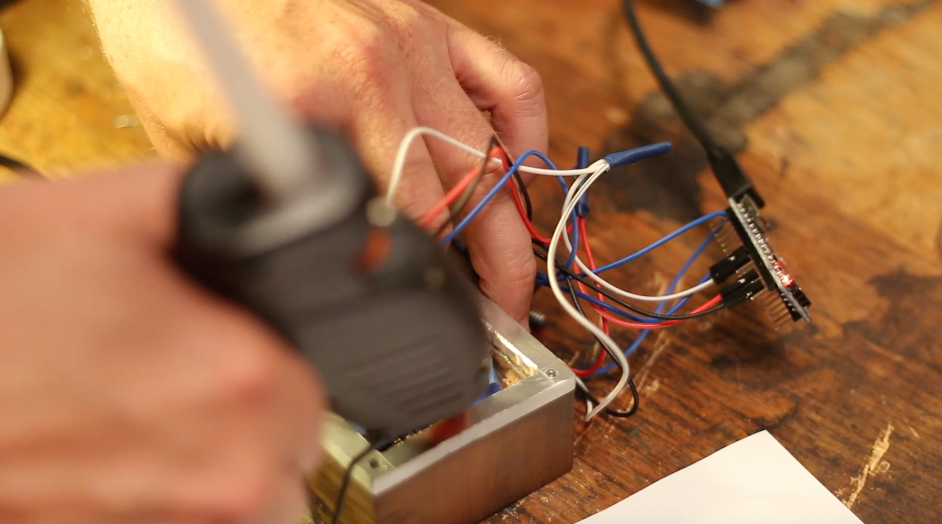

Use the above circuit diagram as a guide to what wire configuration you need. Solder together 12 wires in 4 'Y' configurations. I used female2female prototyping wires. Cover the exposed solder and wires with electrical tape or shrink warp. Reassemble the circuit without the breadboard and verify it's working.
Very carefully hot glue the LED grid to the bottom of the box. This needs to be done when the LED is on so you can make sure the LEDs align with the holes. I used some blue tape to help keep it in place while applying the glue. Insert the rest of the electronics in the box. Use the rotary tool with a grinding disk to grind out a small notch in the aluminum for the USB cable to pass through.
Drill some vent holes in the back plate, screw it back on and your done!
Step 11: Conclusion

Thanks for reading this instructable! I really like how this project combined modern electronics with traditional wood and metal work. Something I'd like to explore more in the future. If you like this instructable please follow me for future projects and checkout my other instructables. Also if you like my video please subscribe to my channel.
Thanks again!
Andrew
Me:
Instagram: @andrew_r_jones
Youtube: @andii1701
Twitter: @andii1701

Participated in the
Lights Contest 2017


