Replace Your Automatic Transmission With A Bunch Of Relays

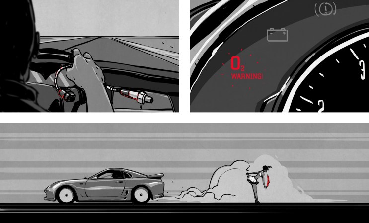
A “Check Engine” light on your dashboard could mean anything from a loose gas cap to a wallet-destroying repair in the offing. For [Dean Segovis], his CEL was indicating a fairly serious condition: a missing transmission. So naturally, he built this electronic transmission emulator to solve the problem.

Some explanation may be necessary here. [Dean]’s missing transmission was the result of neither theft nor accident. Rather, he replaced the failed automatic transmission on his 2003 Volkswagen EuroVan with a manual transmission. Trouble is, that left the car’s computer convinced that the many solenoids and sensors on the original transmission weren’t working, leaving him with a perfectly serviceable vehicle but an inspection-failing light on the dash.

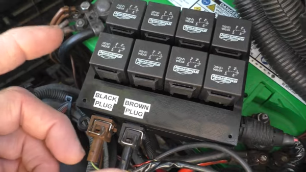
To convince the transmission control module that a working automatic was still installed and clear the fourteen-odd diagnostic codes, [Dean] put together a block of eight common automotive relays. The relay coils approximate the resistance of the original transmission’s actuators, which convinces the TCU that everything is hunky dory. There were also a couple of speed sensors in the transmission, which he spoofed with some resistors, as well as the multi-function switch, which detects the shift lever position. All told, the emulator convinces the TCU that there’s an automatic transmission installed, which is enough for it to give the all-clear and turn off the Check Engine light on the dash.

We love hacks like this, and hats off to [Dean] for sharing it with the VW community. Apparently the issue with the EuroVan automatic transmissions is common enough that a cottage industry has developed to replace them with manuals. It’s not the only questionable aspect of VW engineering, of course, but this could help quite a few people out of a sticky situation.

Continue reading “Replace Your Automatic Transmission With A Bunch Of Relays”

Recreating The “Stuck Throttle” Problem On A Toyota

A few years ago, Toyota was in the news for a major safety issue with a number of their passenger vehicles. Seemingly at random, certain cars were accelerating without concern for driver input, causing many crashes and at least 37 confirmed deaths. They issued recalls both for the floor mats which were reported to have slid forward to jam the accelerator pedal, but this didn’t explain all of these crashes. There was another recall for stuck throttles, which [Colin O’Flynn] demonstrates a possible cause for on his test bench.

While most passenger vehicles older than about 15-20 years controlled the throttle with a cable connected directly from the throttle body to the accelerator pedal, most manufacturers have switched to a fly-by-wire system which takes sensor input from the accelerator pedal and sends that position information to the vehicle’s computer which in turn adjusts the throttle position. This might be slightly cheaper to manufacture, but introduces a much larger number of failure modes to a critical system. Continue reading “Recreating The “Stuck Throttle” Problem On A Toyota”

Saving Fuel With Advanced Sensors And An Arduino

When [Robot Cantina] isn’t busy tweaking the 420cc Big Block engine in their Honda Insight, they’re probably working on some other completely far out automotive atrocity. In the video below the break, you’ll see them take the concept of a ‘lean burn’ system from the Insight and graft hack it into their 1997 Saturn coupe.

What’s a lean burn system? Simply put, it tricks the car into burning less fuel when it’s cruising under a light load to improve the vehicle’s average mileage. The Saturn’s electronics aren’t sophisticated enough to implement a lean burn system simply, and so [Robot Cantina] did what any of us might have done: hacked it in with an Arduino.

The video does a wonderful job going into the details, but essentially by using an oxygen sensor with finer resolution (wide-band) and then outputting the appropriate narrow band signal to the ECU, [Robot Cantina] can fine tune the air/fuel ratio with nothing more than a potentiometer, and the car’s ECU is none the wiser. What were the results? Well… they weren’t as expected, which means more experimentation, more parts, and hopefully, more videos. We love seeing the scientific method put to fun use!

People are ever in the quest to try interesting new (and sometimes old) ideas, such as this hot rod hacked to run with a lawnmower carburetor.

Continue reading “Saving Fuel With Advanced Sensors And An Arduino”

Hypercar Valve Technology On A Harbour Freight Engine

The inlet and exhaust valve timing of a piston engine plays a large role in engine performance. Many modern automotive engines have some sort of variable valve timing, but the valves are still mechanically coupled together and to the crankshaft. This means that there is always a degree of performance compromise for various operating conditions. [Wesley Kagan] took inspiration from Koenigsegg’s camless Freevalve technology, and converted a Harbour Freight engine to camless technology for individual valve control.

By eliminating the traditional camshaft and giving each valve its actuator, it is possible to tune valve timing for any specific operating condition or even for each cylinder. A cheap single-cylinder engine is a perfect testbed for the garage hacker. [Wesley] removed the rocker arms and pushrods, and replaced the stock rocker cover with a 3D printed rocker cover which contains two small pneumatic pistons that push against the spring-loaded valve stems. These pistons are controlled by high-speed pneumatic solenoid valves. A reference timing signal is still required from the crankshaft, so [Wesley] built a timing system with a 3D printed timing wheel containing a bunch of embedded magnets and being sensed by a stationary Hall effect sensor. An Arduino is used to read the timing wheel position and output the control signals to the solenoid valves. With a rough timing program he was able to get the engine running, although it wouldn’t accelerate.

In the second video after the break, he makes a digital copy of the engine’s existing camshaft. Using two potentiometers in a 3D printed bracket, he measured push rod motion for a complete engine cycle. He still plans to add position sensing for each of the valves, and after a bit more work on the single-cylinder motor he plans to convert a full-size car, which we are looking forward to.

People have been tinkering with cars in their garage for as long as cars have existed. [Lewin Day] has been doing a series on how to get into tinkering with cars yourself. With all the electronics in modern automobiles, messing around with their software has become a growing part of this age-old pastime. Continue reading “Hypercar Valve Technology On A Harbour Freight Engine”

A Motorcycle Dashboard Straight From The ECU

Classic motorcycles are the wild west of information displays. Often lacking even basic instrumentation such as a fuel gauge and sometimes even a speedometer, motorcycles have come a long way in instrument cluster design from even 20 years ago. There’s still some room for improvement, though, and luckily a lot of modern bikes have an ECU module that can be tapped into for some extra information as [mickwheelz] illustrates with his auxiliary motorcycle dashboard.

This display is built for a modern Honda enduro, and is based upon an ESP32 module. The ESP32 is tied directly into the ECU via a diagnostic socket, unlike other similar builds that interface with a CAN bus specifically. It can monitor all of the bike’s activity including engine temperature, throttle position, intake air temperature, and whether or not the bike is in neutral. [mickwheelz] also added an external GPS sensor so the new display can also show him GPS speed and location information within the same unit.

[mickwheelz] credits a few others for making headway into the Honda ECU. [Gonzo] created a similar build using a Raspberry Pi and more rudimentary screen but was instrumental in gathering the information for this build. If you’re looking for a display of any kind for your antique motorcycle which is lacking an ECU, though, we would suggest a speedometer made with nixie tubes.

Hackaday Prize Entry: Engine Control Units And Arduinos

The modern internal combustion engine is an engineering marvel. We’re light-years ahead of simple big blocks and carburetors, and now there are very fast, very capable computers sensing adjusting the spark timing, monitoring the throttle position, and providing a specific amount of power to the wheels at any one time. For the last few years [Josh] has been building a fully-featured engine management system, and now he’s entered it in the Hackaday Prize.

The Speeduino project is, as the name would suggest, built around the Arduino platform. In this case, an Arduino Mega. The number of pins and PWMs is important — the Speeduino is capable of running the fuel and ignition for eight cylinder engines.

The Speeduino is designed to do everything an engine control unit can do, including rev limiting (although if you’re building your own ECU, why?), and reading ethanol sensors. Right now [Josh] is working on a beta run of the Speeduino designed for the 1.6L Miata. That’s an excellent platform for firmware performance tuning, and there’s still a lot of work to be done on the firmware side of things before everything’s all set to go. Still, this is a great project and sure to impress the bros at track day, bro.

Wideband Woes And The Junkbox Miata

As ever, I am fighting a marginally winning battle against my 1991 Mazda MX-5, and this is the story of how I came to install a wideband oxygen sensor in my Japanese thoroughbred. It came about as part of my ongoing project to build myself a viable racecar, and to figure out why my 1990s Japanese economy car engine runs more like a late 1970s Malaise-era boat anchor.

I’ve always considered myself unlucky. My taste for early 90s metal has meant I’ve never known the loving embrace of OBD-2 diagnostics, and I’ve had to make to do with whatever hokey system was implemented by manufacturers who were just starting to produce reliable fuel injection systems.

Narrowband oxygen sensor voltage output. The output is heavily dependent on sensor temperature and highly non-linear, making these sensors unsuitable for delivering a true AFR reading.

This generally involves putting in a wire jumper somewhere, attaching an LED, and watching it flash out the trouble codes. My Mazda was no exception, and after putting up with a car that was running rich enough to leave soot all over the rear bumper, I had to run the diagnostic.

It turned up three codes – one for the cam angle sensor, and two for the oxygen sensor. Now, a cam angle sensor (CAS) fault will normally prevent the car running at all, so it’s safe to assume that was an intermittent fault to keep an eye on.

The oxygen sensor, however, was clearly in need of attention. Its job is to allow the engine control unit (ECU) to monitor the fuel mixture in the exhaust, and make sure it’s not too rich or too lean. As my car was very obviously running too rich, and the diagnostic codes indicated an oxygen sensor failure, a repair was in order.

I priced up replacement sensors, and a new oxygen sensor could be had for under $100. However, it wasn’t exactly what I wanted, as not all oxygen sensors are created equal. Cars in the 80s and 90s typically shipped from the OEM fitted with what’s called a narrowband oxygen sensor. These almost always consist of a zirconia dioxide cell that outputs a voltage depending on the difference in oxygen concentration between the exhaust gas and the free air. These sensors generally sit at 0.45 V when the fuel mixture is stoichiometric, but rapidly change to 0.1 V in a lean condition and 0.9 V in a rich condition. The response is highly non-linear, and changes greatly with respect to temperature, and thus is only good for telling the ECU if it’s rich or lean, but not by how much. ECUs with narrowband sensors tend to hunt a lot when running in closed loop O2 control – you’ll see an engine at idle hunt either side of the magical 14.7 stoichiometric air fuel ratio, never able to quite dial in on the correct number.

As I intend to switch to an aftermarket ECU in the future, I’ll need to tune the car. This involves making sure the air/fuel ratios (AFRs) are correct, and for that I need to be able to properly measure them. Just knowing whether you’re rich or lean isn’t enough, as often it’s desirable to run the engine intentionally rich or lean at certain engine loads. To get a true AFR reading requires fitting a wideband oxygen sensor. These are a little more complicated.

Continue reading “Wideband Woes And The Junkbox Miata”