

Introduction: Programmable Automatic Blind Opener


A while ago I changed my room around, which made opening and closing the roller blind harder. Like most people, I close the blinds when it gets dark and I have to put the lights on. Similarly, I open the blind in the morning when I wake to let the sun in. The way in which I have changed my room around makes accessing the pull-cord for the blind difficult. I therefore decided that I needed an automatic way of opening and closing the blind.
Although not part of my original design concept it can be used as a security device. i.e when on holiday, use the automatic function to open and close the blind to give the impression of being home.
The solution was to create a way of automatically opening or closing the blind, when needed, or at predetermined times.
Therefore the blind opener should be able to do the following :-
- Have high reliability - for automatic operation
- Be flexible in its use - so that I can change the time when the blind automatically opens/closes.
- Have a manual override - so that the blind can be opened or closed when needed.
- Be compatible with my current roller blind – so I don’t need to buy a new one.
- Low cost – I do not want to spend excessive costs on the project.
- Be safe - Ensure that the external power supply is suitable and is working within its manufacturers guidelines.
I choose to use Arduinos as the controllers because of the wide-range of library support and low cost.
I used Fusion 360 to design and model the 3D printed parts, as it's an easy to use, affordable CAD program that makes designing parts quick and easy. Fusion 360 is also well supported and documented because of this, I tend to prefer it over other 3D modelling applications.
The blind opener consists of a DC motor that controls the blind pulley via a custom-made gear system. The blind is operated by a control panel, allowing you to either open or close the blind or to set the automatic timing function. A RTC (Real time clock) is used to add the automatic timing function of the blind opener. The start and stop point of the blind is controlled by coloured strips at the top and bottom of the blind, these are detected by a sensor.
The cost of the project is around £30 - £70 (approx. $38 - $90) depending on what parts you already have and where you source any needed parts. I have not included any specific tool costs. For this Instructable, I will assume that you are confident with DC electronics and have a basic understanding of Arduinos.
I should mention that this is a fairly lengthy Instructable, but I wanted to make sure that I covered as much as I could and I suggest you read to the end before starting. I have included as much information as I can and I hope you learn something as well as enjoying this Instructable.
Lastly, I take no responsibility or liability for any loss or damage to personnel or property.
With all of that out the way, lets build!
Step 1: Overview


Basically, the blind opener works by using a DC motor to drive a custom made gear. The cord of the blind fits around this gear and as it turns, the blind is pulled up or down, depending on its direction of rotation.
Motor:
The motor's direction of rotation is controlled by connecting it to two relays, these are used to reverse the polarity of the supplied voltage, thus changing the motor's direction. In essence, we are using an H-Bridge.
Control Panel:
The control panel is laser cut from Acrylic sheet and incorporates a 20x4 LCD (Liquid Crystal Display) and four buttons, which are used to program the blind opener.
Blind Direction and State:
The directional movement of the blind is controlled by the use of red and green strips of paper. These strips also act as a trigger to stop the movement of the blind. They are positioned at the top (red) and bottom (green) of the blind. A sensor monitors the blind for the presence of these strips, and when detected, depending on colour it sets the direction of the blind (either up or down) for its next movement.
Arduino (x2):
The reason for using two Arduinos is that one Arduino can be completely dedicated to monitoring the colour sensor operation.
Main Arduino:
The main Arduino is responsible for driving the LCD, RTC, Motor and checking the other Arduino. The Arduino controls the motor by using an electrically isolated relay module which is required as the motor runs off 12v, whereas the Arduino runs of 5v. To simplify the design and wiring, a voltage booster is used to convert the 5v from the Arduino's power pins to the 12v that the motor needs. We can use a boost converter as opposed to an external power supply because the motor only requires 150mA to run which is quite a small amount of current compared to other motors.
Secondary Arduino:
The secondary Arduino is used to monitor the sensor. It is dedicated to this function and requires only a small bit of code. It is not interrupted by other functions that may cause it to miss-detect the strips on the blind. This Arduino tells the main Arduino where the blind is by pulling one of two signal wires high. One signal wire is pulled high when the blind is fully up, and the other is pulled high when the blind is fully down.
Step 2: Fusion 360


I used Fusion 360 to model the printed the parts. If you are interested in how the blind gear was modelled, or you need to modify the file to accommodate your blind cord, read on - if not skip this and the next step.
To design the gear, I needed to know three main things:
- The distance between the center of the balls on the chain - this was measured to be 11.4mm.
- The diameter of the balls on the chain - this was measured to be 5mm.
- The rough diameter that I wanted the gear to be.
I first picked a rough diameter of 30 mm for the gear as this was small, reducing the size of the final unit and close to the size of the gear on the roller blind, meaning that the system would turn on a 1:1 ratio.
With this rough diameter, I then needed to work out how many balls could fit on the gear - however as there is cord between the balls, this also needs to be accounted for so that it is kept taught on the gear.
As the gear is circular, we can use pi (π) for our calculations. The formula for working out the circumference of a circle is π * D. As the chosen diameter is 30 mm, multiplying this by pi will give us 94.248, which is the circumference of the gear.
To find the distance between the center of each ball on the chain, we can simply measure from the same side edge on two different balls using a set of Vernier callipers, as shown in the diagram above. I also measured the diameter of the ball to be 5mm.
With this data, I simply divided the circumference of the gear by the distance between the balls' centres to find out how many equally spaced grooves can fit. The calculation was: 94.248 (circumference) / 11.4(distance) = 8.267. However, we need whole numbers so rounding this number down to 8 is fine.
From this, we now know that 8 grooves need to feature on the ball.
As shown above, to allow the gear to accommodate for the 'D' shaft, I measured the diameter without the spline first, which was 6 mm. I then measured it with the spline and it came to 5.5 mm. Therefore we know that the spline's indent is 0.5mm.
Step 3: Fusion 360 Designing


To design the gear follow these steps, referring the step numbers to the numbers in the diagram.:
- Draw a circle that has a diameter of 30 mm in Fusion 360.
- Draw a 8-sided polygon of any size, with its center point being the same as the circles. (Enter the amount of sides by pressing tab to select the sides parameter)
- Use the dimension tool (by pressing 'd') to select one side of the polygon. Enter 11.4 (the distance between the blind cord balls) into the parameter box.
- For each point of the polygon, draw a circle with a diameter of 5mm.
- Delete the centre circle and draw a new one, which will be slightly larger, making sure that the circumference of this circle intersects the centre points of the 8 smaller circles.
- Trim ('t' on the keyboard) the outer sections of the smaller circles and delete the internal polygon.
- Trim the sections of the bigger circle's circumference that crosses into the smaller circles.
- Draw a circle in the centre of the gear, with a diameter of 6 mm
- Draw two vertical lines: One inside the inner circle and another at the edge of the inner circle. Use the dimension tool to alter the distance between these lines to be 0.5mm.
- Trim the lines excess, as well as the circumference of the inner circle that has not been intersected by the inner line, so that you are left with a 'D- Shape'.
- Exit sketch mode and extrude the gear so that it is 6mm thick.
- Export the gear as a .stl and print.
Step 4: Parts List


To build the blind opener, you will need the following parts and tools. I have compiled a table with links and prices to make it easier to source these parts. Please note these prices were only current at the date of publication and are for guidance only.
Components:
| Part (As labeled in diagram) | Retailer & Link | Cost |
|---|---|---|
| 1- Arduino Prototyping Board | Amazon | $5.99 |
| 2 & 3 Arduino UNOs/ Leonardos * | approx: $18 - $24 | |
| 4- RTC Module | $5.59 | |
| 5- Relay Module | $6.99 | |
| 6- DC Boost Converter | $10.29 | |
| 7- 4x 12.4mm x 12.4mm Rectangular PCB Switches | approx: $4.30 | |
| 8- Adafruit TCS34725 | approx: $7.95 - $13 | |
| 9- Strip board | $5.75 | |
| 10- Jumper wires | $7.97 | |
| 11- 20x4 I2C LCD | $10.99 | |
| 12- High torque 12v DC motor (30RPM) | $13.22 | |
| 13- 5m of 6 Core alarm cable | $2.02 per meter |
You will also need a 5v - 12v Power Supply capable of powering the Arduino.
* Most Arduinos will work, as long as they are based on the open-source model and support the mentioned libraries.
Tools/Other Parts:
| Tool | Retailer & Link | Cost |
|---|---|---|
| 1- 2x 3mm Acrylic sheet | Amazon | $9.65 |
| 2- 1x Marker Pen | - | - |
| 3-Needle-nosed pliers | $5.70 | |
| 4- Screw drivers | $5.94 | |
| 5- M3x10mm hex screws | $4.03 | |
| 5- M3 nut | $5.14 | |
| 5- M3x5mm hex screws | $7.32 | |
| 5- M3 washers | $6.84 | |
| 6- Crimp tool | $23 | |
| 7- Silicon | $4.36 | |
| 7- Silicon gun | $8.99 | |
| 8- Female crimps | $6.99 | |
| 8- Blind Cord * | $1.70 | |
| Wire Strippers | $16.17 | |
| Heat-Shrink Tubing 2.5mm i/d, 2:1 shrink ratio | - | - |
| Insulation tape | $4.67 | |
| Metric Allen keys | $6.56 | |
| Hookup Wire | $6.18 | |
| Hot Glue Gun | $9.99 | |
| Soldering Iron and Solder | $19.99 | |
| Multi-Meter | $13.99 | |
Bradawl | $3.95 | |
| Drill | $49.00 | |
| Metric Drill Bits | $9.99 |
For the calibration phase, you will need either a USB cable that reaches form the blind to your computer OR a laptop.
I live in the UK, but to help our American cousins/friends I have tried, where possible to include American suppliers and rough prices. Please bear in mind that all sizes are in Metric.
If you are having difficulty sourcing any of the parts, comment and I will try to help.
Notes:
*The design of the gear in this project was based on the use of this cord and has been tested to work.
Step 5: 3D Printed Parts
The following parts need to be 3D printed at 0.25 resolution and 25% infill. I have included a Fusion 360 file for the colour sensor bracket, in case you need to modify the height.


Step 6: Motor Assembly


Print the following parts in ABS with a resolution of 0.25 and an infill of 25%. The gear can be optionally laser cut, if the 3D version is not strong enough.
Cover.stl
Case.stl
Gear.stl
Using two of the M3x10mm screws, partially screw them into the holes on the case. Then clip the case onto the end of the motor and align the two screws with the two vertically aligned holes on the motor, as shown in the diagram.
Tighten the screws, ensuring that they sit flush.
Now, slip the gear (either 3D printed or laser cut) onto the motor shaft, taking note of the 'D' alignment required.
Finally, line up the cover and screw it down using the other two M3x10mm screws.
Step 7: Soldering the Motor

Solder two 25 cm lengths of the hook-up wire to the motor lugs. Then thread a 10 - 15mm length of heat-shrink tubing to cover each motor lug and shrink to ensure it forms a good electrical isolation.
Step 8: Component Mark-Up


We now need to mark the position of the various components on the Acrylic sheet, prior to mounting.
- First, take the Acrylic plate and place it on your windowsill, under your blind. Now place the motor on the Acrylic plate, ensuring it is vertically in line with the blind's cord, as shown in the diagram. While holding the motor assembly on the Acrylic plate, lift the plate up and flip it over. Mark the position of the mounting holes on the motor assembly onto the Acrylic.
- Next, place the two Arduinos on this plate, at the opposite end to where the motor is mounted so that the Arduinos are vertically in line with each other. Leave a gap (roughly 1.5 cm) between the two Arduinos. Next place the relay module next to the bottom Arduino, with another gap (roughly 2.5cm). Add the boost converter next to the relay module, with another gap (roughly 1.5cm). Use the photo attached above as reference. Motor alignment with the bottom of the blind is important, the exact positioning of the other components is not as critical. Finally use a marker pen to mark each of the holes indicated in the diagram onto the Acrylic plate.
Step 9: Drilling


Remove all of the components and use a bradawl to mark out the center of each of the marks you just made. Apply firm pressure to create a slight indent. This will stop the drill slipping when drilling the holes. Be careful not to slip and cause injury. Then use a 3mm drill bit to drill out the holes, take care not to melt the Acrylic by using the wrong drill speed. If needed, use a 7mm drill bit to remove any burs, but use your hands to turn the bit - not the drill.
Step 10: Mounting - Relay Module


Attach the stand-offs for the relay module to the Acrylic
plate, as shown in the illustration above. Ensure that you use the washers to prevent the Acrylic plate from cracking.
If necessary tighten the nut with the needle-nosed pliers, but be careful not to over-tighten as this could also crack the Acrylic plate.
Finally place the relay module over the stand-offs and use the four M3x5mm screws to secure it in place.
Step 11: Mounting - Arduinos and Boost Converter


Using the diagram above as a reference:
To create stand-offs for the Arduinos and Boost Converters:
For each of the 10 holes (2 x 3 -Arduino, 1 x Boost Converter)
- Places a washer on each of the 10 – M3x10mm hex-bolts.
- Push each hex-bolt/washer through the 10 holes in the Acrylic plate.
- Place another washer on each of the 10 hex-bolts so that it sandwiches the Acrylic plate.
- Screw a M3 nut finger tight onto each of the hex-bolts.
After all the spacers are in place mount the 2 Arduinos and the Boost converter in their corresponding positions. Next place a washer on each of the spacers on the top of each board and secure with a nut. The above diagram illustrates the resulting mounted boards.
Step 12: Mounting - Motor

The motor is mounted by placing a washer on each of the 2 M3x10mm hex bolts, then flipping the Acrylic plate over and aligning the holes on the gear assembly. Secure the motor assembly to the Acrylic plate with the hex bolts and washers.
Step 13: Wiring
Although not necessary, good cable management makes for a better looking finished project. It also helps diagnosing faults and will give you a better understanding of how each component connects together. Use cable ties where possible and don’t completely separate the jumper wires in the ribbon cable.
Step 14: Wiring - Signal Wires


To wire up the relay module, you will need 6 male-to-female jumper wires. Peel a ribbon of 6 wires from the ribbon cable but don’t separate them into individual jumper wires. Plug the six wires into the relay headers, ensuring that the jumpers or wires do not cross over as shown above. The colours you use are not that important, just make sure that you can identify each wire and you also know which relay pin it is on.
This is also a good time to put the breadboard shield on the top Arduino board. Just ensure that the pins are lined up correctly and push it down.
Using the above picture as reference, route the wires in a sort of 'z' shape, as shown above. It's easier to bend the wires down near the connectors so they touch the plate, lie them flat and then fold them back up at the other end so they can be plugged into the Arduino.
Use the following chart to connect the relay module to the Arduino. (NOTE: the colour of your jumper wires may differ).
| Relay Module | Arduino UNO |
|---|---|
| GND | GND |
| IN1 | 7 |
IN2 | 6 |
IN3 | 5 |
| IN4 | 4 |
| VCC | 5v Rail on Shield |
As previously mentioned, the second Arduino tells the main Arduino where the blind is by using two signal wires. Route the male to male jumper wires under the main Arduino, by threading them underneath, as seen in the image. Connect these wires as shown below:
| Primary Arduino (UNO) | Secondary Arduino (Leonardo) |
|---|---|
| 4 | 2 |
| 5 | 3 |
Step 15: Wiring - Motor Cables


Before wiring up the motor, first route the motor wires next to the relay module wires.
To do this, keep these wires flat and mark two dots 2 mm from either side of the wires. Drill these holes out with a 2.5 mm drill bit. Then thread the tail of a cable tie into one hole, loop it underneath the Acrylic and thread it back out the other hole, as shown in the diagram. Ensuring the wires are flat, move the tie so the square rests on one of the holes and pull the tail to remove all slack, as shown. Now tighten the cable tie and snip the tail of with some cutters.
Continue routing the motor wires by curving them around the relay module's corner, keeping them flat and un-twisted - especially round the bend.
Repeat the cable-tie installation process explained above to install an additional cable tie. Finally strip the end of both motor cables.
Step 16: Relay Wiring

Connect the motor to the relay module.
Connect a motor wire to the common connection on each of the two bottom relays (as shown in the diagram). Do this by unscrewing the screw in the terminal block, inserting the wire and re-tightening it.
Note: We do not need to worry about motor polarity as we will configure this in the code during calibration and testing.
Step 17: Relay Wiring - Power (Negative)


We now need to connect the relays to the boost converter.
We will use the ‘Common both Normally Closed’ (NC) contacts on the bottom two relays.
Strip the ends of two wires one short and one long.
Use the short length of wire to connect the NC terminals on each of the bottom two relays.
Use the long piece of wire to connect one of the relay NC terminals to the GND terminal of the Boost Converter.
This wiring will ensure that both motor contacts are grounded by default during operation.
Then, repeat the process above but for the Normally Open (NO) contacts on the relays - this time going to the positive output terminal on the boost converter, ensuring this wire is also under the PCB, as illustrated above.
Step 18: Relay Wiring - Final Check

The relay wiring should now look like the image above.
Step 19: Boost Converter Wiring

To minimize heat and to increase reliability/safety, the boost converters power will also be controlled by a relay. Connect a wire between the positive input on the boost converter and the Normally Open (NO) connection on the 2nd relay from the top, also making sure that this wire is routed under the PCB.
Step 20: Final Relay/Boost Converter Wiring

Add a longer jumper (orange in the picture) to the Common terminal on the 2nd relay from the top. Route the other end under the Relay Module and connect it to the VIN pin on the Arduino UNO. This will give us direct power from the DC in jack and will mean that we do not need to worry about current draw.
Next, connect a longer jumper (white in the picture) to the GND terminal on the Boost Converters input voltage terminal. Again, route the other end of the jumper under the Relay Module but this time plug the jumper into the GND rail on the UNO.
Finally connect two longer jumpers (green in the picture) to the Common and Normally Open (NO) terminals on the top relay. Thread these two jumpers under the Relay Board, leaving the ends unconnected for now.
Step 21: LCD Panel


The LCD panel is laser cut out of 3 mm Acrylic Sheet. I choose to use purple Acrylic as it contrasts the blue LCD and green buttons well.
For the button spacer plate, I used 6 mm Acrylic but two stacked 3 mm pieces would also work. You will need to chamfer one of the long edges on the spacer (as indicated) either with a file or a sander.
I have included the files needed to laser cut the parts for the control panel at the end of this Instructable. If you don’t have access to a laser cutter, there are many companies that provide a cutting service.
Before assembly, please remove the protective film.
Step 22: Panel Assembly


The box is held together with 'T-slots' which allow the control panel to be assembled with screws. The advantage of this is that assembly is easier, while allowing the control panel to be stronger and more robust.
To begin assembly, first put a washer on each of the 20 M3x10mm hex screws, followed by a nut. Keep the nut and the end of the thread flush (as shown), as we need as much distance as possible between the nut and screw head for assembly. Also, set aside the button spacer and the panel with the cut-out for the screen.
Drill two holes with a 4 mm drill bit on one of the side panels, leaving a 3 mm gap between them.
Put the Control Panel together by slotting the top and bottom panels into the longer sides of the back plate, followed by slotting the 2 side panels into the shorter sides of the back plate (you may have to slot these in sideways if the top and bottom panels cause an obstruction).
To put a screw in the 'T-slot', slide the nut into the rectangle (as seen in the picture). There should be enough clearance for the hex nut's head and washer to slide over the top of the Acrylic edge. When seated properly, tighten the hex nuts finger tight to avoid cracking.
Repeat this process to install the other screws, ensuring that you do not install the panel with the LCD cut-out yet.
Step 23: LCD Plate


To mount the LCD module, first insert the 4 M3x10 screws with M3 washers into the four holes on the Acrylic plate. Make sure that the screw heads and washers are on the surface of the Acrylic that has the letters engraved onto it. Next place a M3 washer over each screw, followed by a nut and tighten down finger tight.
Now, place another M3 nut on each of the screw - but stop screwing the nut when it is half way down the screw thread. Also add a M3 washer to the thread so it rest on the nut. This acts as a platform on to which each mounting hole of the LCD module will rest.
Place the LCD module over of the 4 screw threads, ensuring that the red I2C interface board is on the side without the button cut-outs (marked on the image).
Finish by adding a washer to the emerging screw thread, so that the washer is on top of the PCB, followed by another M3 nut. Tighten the nut down carefully.
If the screen is not flush with the panel (the side with the letters engraved), screw the resting nuts down slightly and re-tighten the top nut until it is flush.
Step 24: Button Panel - Signal Cables

Decide where you want the control panel to be mounted and measure from its position to the position of the Blind Opener. Please allow for any cable routing i.e. under windows seals, around corners etc. add 2.5cm to this length to allow for internal wiring. Then cut two lengths of the 6-core alarm cable to this length.
Set aside one length of the cable you just cut. With the other length of cable, strip the outer sleeve back 2.5cm, this will carry the signal for buttons 1, 2, 3, 4 and GND. As we will only use 5 of the 6 wires, trim the white wire back.
Important: Mark this cable approximately 2cm from each end with insulation tape. This is so we can easily identify it later on in the build.
Step 25: Button Panel - GND Connections


The buttons are mounted on a piece of strip-board that is then attached to the control panel via an Acrylic spacer. The advantage of this is that it allows the buttons to sit flush against the control panel, making the unit more sleek.
Cut a piece of strip-board that is roughly 60 mm x 20 mm and install the buttons so that all of their pins follow the same pattern (as shown in the diagram). Use the spacer to ensure they are all straight and line up. Make sure that the buttons are as close one of the long edges as possible, so that the strip-board will not touch the LCD module when mounted. Solder these buttons in place, and trim the legs afterwards.
Join every other pin together with a jumper (shown as the black dots on the drawing), as shown by the highlighted yellow lines in the photo or the black lines on the diagram.
Solder the wire on the surface of the track, as we need the top of the board to be clear for the signal cables.
Step 26: Button Panel - Signal Wiring


Starting with the button on the left (labelled as button 1), insert one of the wires from the alarm cable through the top of the breadboard, so that the wire protrudes from the track that the buttons signal pin is connected to. Solder this wire in place. The colour of the wire does not really matter, but if you have black - reserve it for ground.
Note:I have marked the button signal pins, the track patterns (in orange) and the wires in the diagram.
Repeat this process, using a different wire each time for the remaining buttons. For the ground wire, solder it onto any track that the common jumpers are soldered to.
Here are the connections, note that the ascending button number starts from the right button:
| Button No. | Wire Colour |
|---|---|
| Button 1 (left) | Green |
| Button 2 | Yellow |
| Button 3 | Red |
| Button 4 (right) | Blue |
| GND | Black |
Tip: If the wire breaks or you make a mistake, you can solder it to the surface of the track instead
Step 27: Button Panel - Mounting

To mount the buttons, first use the hot-glue gun to glue the spacer to the top of the strip-board. The best way to do this is to butt the spacer on at an angle, fill the gap with glue then push it down (shown as step 1 in the diagram). Then fill the chamfer with glue, care not to heat up the wires with the glue gun's nozzle (step 2 in the diagram).
Let this cool then making sure that the wires face towards the edge and not the LCD panel, press fit the buttons into the cut-out.
Once you are happy that everything fits, remove the PCB, apply hot glue to the top of the bracket, then firmly press it back into place (step 3 in the diagram).
Finally, apply hot glue around the spacer on the front panel to reinforce everything (step 4 in the diagram). Optionally, apply extra glue to the wires on the PCB to give them extra strength.
Step 28: LCD Cable


With the other length of alarm cable that you cut. Strip back the outer sleeve about 6 cm on one end. Then shorten the yellow and white wires by 4 cm. Strip these individual wires and crimp a female crimp to each wire
Cut 6 x 20mm lengths of heat shrink and place one piece over each of the crimped wires. Make sure the end edge of the heat shrink is flush with the bottom of the crimp and apply heat to shrink.
Tip: Dip the heat shrink and crimp into boiling water to shrink and pat dry with kitchen roll.
Step 29: Connections

To finish the panel assembly, first remove the back-light jumper from the red I2C controller board. Plug in the female crimps from the yellow and white wires onto these headers instead. This controls the back light and by removing the jumper, and replacing it with the wires, it allows us to turn it on or off. The blue and green cables carry the I2C data for the screen. We use this method as it reduces how many wires are needed to interface with the display.
Now, connect the wires as shown in the table below:
| LCD Header | Wire Colour |
|---|---|
| GND | Black |
| VCC | Red |
| SDA | Blue |
| SCL | Green |
Step 30: Final Panel Assembly

Thread the alarm cable through the holes on the side panel that was drilled through earlier. Do the same for the button panel cable as well.
Finally, attach the front panel to the top of the case. As you do this, gently pull the alarm cables to remove any excess length in the case. Use the remaining four M3x10mm screws to secure the front panel to the rest of the case.
Step 31: Colour Sensor Preparation

To prepare the colour sensor, solder the headers horizontally onto the holes (as shown as step 1 in the picture). The reason for this is that there is not enough space between the blind and the ceiling for the headers and cables if soldered the normal way.
Next, measure how much cable is needed to reach from the top of the blind to where the blind opener is to be mounted. Again, add 15 cm to this final length then cut the cable.
Strip back the outer sleeving, and cut the blue wire back. Strip each individual wire (step 2 in the diagram). Crimp these wires with female crimps and insulate each crimp with heat shrink.
Tip: You can use insulation tape instead of heat shrink.
Check the bracket fits by placing the sensor in it, ensuring that the pins are on the chamfered side. You may have to apply some gentle pressure to get the sensor to sit properly. If the gap is too small or the sensor sits unevenly, file the sides out slightly. Likewise if the gap is too big, use some Silicon to hold it in place.
Finally, wire up the connections as shown:
| Colour Sensor | Wire Colour |
|---|---|
| VIN | Red |
| GND | Black |
| SCL | White |
| SDA | Yellow |
| INT | Green |
| 3v3 | Not Connected |
| LED | Not Connected |
Note: The pins marked 3v3 and LED are not used
Step 32: Colour Sensor Bracket


The colour sensor is mounted via a 3D printed bracket which is fixed to the ceiling.
To mount the bracket, put a blob of Silicon on the ceiling in line with the blind bracket, so that when the blind is installed the bracket is positioned over the center of the blind.
Note: I’m using silicon to mount the sensor as its easier than drilling and screwing the sensor to the ceiling.
Then push the bracket onto the silicon, pointing the chamfer towards the window, this is where the cables will come out.
Tip:It is best to leave the bracket overnight (24 hours) for the silicon to cure before use.
Step 33: Roller Blind Calibration

After the Silicon has cured, install the colour sensor making sure that the wires come out from the chamfered edge. You can optionally use a cable clip hammered into the ceiling or wall to move the cable out of the way.
Roll the blind down to the required closed position and mark the blind under the colour sensor with a pen (a small dot should do). This will become the blinds closed position.
Now, roll the blind up to the desired open position and mark another point, as above.
Step 34: Roller Blind Markers

Print the attached PDF files and cut out the two-coloured marker strips.
Cut two strips of double sided tape to the same size and apply to the coloured strips leaving the backing on the tape.
Remove your blind and lay it out flat. Find the lower mark (open position) then peel the backing off the green strip and position it so that the strip is cantered over the mark.
Then find the upper mark (when the blind is down) and repeat the above process but with the Red strip.
Finally, roll up the blind manually and re-install it - the red tape should be under the colour sensor.
Attachments

Step 35: RTC

The final component to add is the RTC (real time clock) as mentioned before, this will use the I2C bus.
If you are using the RTC from the provided link the pins should read (from the left) 32K, SQW, SCL, SDA, VCC, GND.
Start by carefully bending the RTC's pins so that they are straight and not at a right-angle. We need to do this as the RTC is very tall and susceptible to being knocked out of the breadboard as well as blocking the headers for the Arduino.
Step 36: RTC - Wiring


To wire the RTC, first insert it into the top left corner of the breadboard, remembering where the ground header pin of the RTC is positioned (marking the breadboard is a good idea) and then remove the RTC.
Cut a length of wire, adding 10mm to the final length, that reaches from the GND rail on the shield to the GND row on the breadboard. Strip 5mm off each end of the wire and bend each at a right-angle. Then insert one end of the wire into the GND rail, and the other end into the GND row on the breadboard, as shown.
Do the same for the VCC connection. This connection is to the left of the GND row, as shown as the red strip in the diagram.
As the LCD display and the RTC must connect to the I2C bus we will need to dedicate two rows on the breadboard to act as a bus. Do this by picking two rows in the bottom right region of the breadboard that are not obstructed by other components.
1. Route a jumper from pin A5 on the UNO (or pin 3 if using an Arduino Leonardo) to whichever row, of the two you just picked, is closest to the GND rail on the shield. This row will act as a bus for the SCL data (blue wired in the diagram).
2. Connect another jumper from pin A4 (or pin 2 if using an Arduino Leonardo) to the other row you picked. This line is a bus for the SDA (green in the diagram).
3. Connect a jumper from the SDA bus that you made to the row that is next to the RTC's VCC line (red).
4. Then add another jumper by connecting it from the SCL bus that you also made to the fourth RTC row.
Finally check your wiring by referencing the picture and then install the RTC module, ensuring that all the pins line up correctly.
Step 37: Pull-Up Resistors


We need to add pull-up resistors to the I2C bus as these stop the signal from floating and giving the Arduino a false signal. Take the two 4.7K resistors (Yellow, Purple, Red) and connect one leg of each to the SDA and SCL bus that you just made.
Then connect the other end of each resistor to the same row elsewhere on the breadboard. Add a jumper between this row and the VCC rail, as shown.
Step 38: Control Panel Cables Preparation


For the other end of the wires coming from the control panel, strip back the sleeving to expose the 6 individual wires, ensuring that you do not remove the mark from the marked wire.
For the marked wire, cut back the white wire, strip, crimp and insulate the other 5 wires.
For the unmarked wire coming from the control panel, strip, crimp and insulate all 6 wires.
Do the same for the alarm cable coming from the colour sensor, cutting back the blue wire.
I will assume that the colour of the jumper wires and the alarm cable wires are the same, as it makes it easier to understand when reading.
Step 39: Button Connections

The buttons are wired up to the Arduino headers as shown using the previously marked cable:
| Wire Colour | Arduino Header |
|---|---|
| Blue | 12 |
| Red | 11 |
| Yellow | 10 |
| Green | 9 |
| Black | GND |
Step 40: Display Connections

We will now connect the display to the blind opener.
Using the un-marked cable that is connected to the LCD module, connect the red wire to the +5vrail. Then connect the black wire to the GND rail.
For the data lines, connect the green cable (SCL) to the SCL bus you made earlier.
Also, connect the blue jumper (SDA) to the SDA bus that you made, as shown in the picture, labelled as ‘SDA line’.
Step 41: Cable Tidying

Remove the bottom Arduino and connect the yellow and white wires from the LCD cable to the two jumpers coming from the relay module.
Then lie the two alarm cables and use tape to keep them in place and flat.
Step 42: Bottom Arduino
Put the bottom Arduino back, securing it with a M3 washer and M3 nut on each screw. Make sure that the cables do not cause the Arduino to flex. If they do, add some more washers to the screws before placing the Arduino on top.
Replace the signal wires that are connected to the top Arduino. Here are the connections again:
| Primary Arduino (UNO) | Secondary Arduino (Leonardo) |
|---|---|
| 4 | 2 |
| 5 | 3 |
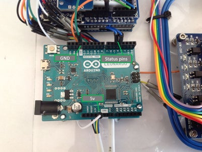
Then connect a jumper between 5v on the top Arduino and 5v on the bottom Arduino. Ensure that the cables go to 5v and not VIN as this could damage the Arduino. Follow this up by connecting another jumper between GND on the top Arduino and GND on the bottom Arduino.
As the colour sensor is also connected to the bottom Arduino, this also needs to be wired up. To do this, follow the connections below, referring to the Arduino type that you are using:
| Wire Colour | Arduino LEONARDO | Arduino UNO |
|---|---|---|
| Red | VCC | VCC |
| Black | GND | GND |
| White | 3 (SCL) | A5 (SCL) |
| Yellow | 2 (SDA) | A4 (SDA) |
| Green | 6 | 6 |
| 3v3 | Not used | Not used |
| INT | Not used | Not used |
Note: pins 3v3 and INT are not used
Step 43: Arduino IDE Preparation


Make sure you have the latest Arduino IDE downloaded and installed. To download and install the 3 libraries used, first open library manager in the Arduino IDE (Sketch> Include Library> Manage Library) and type in "RTClib" (without the quote marks) to the search bar.
Install the library released by Adafruit by selecting the latest version from the drop-down menu and clicking install, as shown above.
Repeat this process to install the RTCs library but type in "RTClib" instead (without the quote marks), as shown.
The last library to install is for the I2C LCD, however this library has to be downloaded.
First, click here to download the zip file. When it is downloaded, open the Arduino IDE and navigate to Sketch> Add File.
Then browse to the location where the downloaded .zip file was saved (in the downloads folder by default), select the .zip file and click 'open'.
Step 44: Colour Sensor Calibration


The bottom Arduino tells the two coloured strips on the blind apart by looking for a specific colour difference in the colour sensor readings. It does this by checking the readings coming from the colour sensor against values that are found from calibrating the blind, to see which strip has been detected.
We will now find the values that need to be typed in to the code by looking at the colour sensor readings when the two strips and blind material are underneath it.
To do this, simply upload the attached code to the bottom Arduino, selecting which board you are using through: Tools> Board> .
Then open the blind so that the green strip rests underneath the colour sensor. Open the serial monitor through Tools > Serial Monitor or by pressing Ctrl + Shift + M
Wait 5 or so seconds so that the values have stabilized, then write down a value from each column (R, G , B and C), making sure you record these values as being for the green strip.
Note: There may be variations in each column but these should only vary by about 10 - 20, which is fine as the code accounts for this.
Then roll the blind down (so that the red strip is underneath the sensor) and record these new values. Make sure you leave at least 5 seconds for the values to stabilize. Again, ensure that you write down that these values are for the red strip.
Finally roll the blind up half-way so that the normal blind material is under the sensor. Leave 5 seconds and record these values, label them as 'Normal'.
Code:
The code itself can be copied from below, and pasted into the Arduino IDE, or downloaded as a .ino file and imported into the Arduino IDE:
/* Code for Automatic Blind Opener Calibration -- by DIYtronics: <a href="https://www.instructables.com/member/diytronics/"> https://www.instructables.com/member/diytronics/
</a>
 *  Using Adafruit TCS34725 colour sensor library : <a href="https://github.com/adafruit/Adafruit_TCS34725"> https://www.instructables.com/member/diytronics/
</a>
 */

#include <Wire.h>
#include "Adafruit_TCS34725.h"

Adafruit_TCS34725 tcs = Adafruit_TCS34725(TCS34725_INTEGRATIONTIME_700MS, TCS34725_GAIN_1X); //Initialise sensor

void setup(void) {
  Serial.begin(9600); //Setup Serial

  if (tcs.begin()) { //If sensor fetected
    Serial.println("Sensor Succesfully Detected"); //Notify user
  } else { //If sensor not found
    Serial.println("No TCS34725 found ... check your wiring"); //Notify user
    while (1);
  }
}

void loop(void) {
  uint16_t r, g, b, c, colorTemp, lux;

  tcs.getRawData(&r, &g, &b, &c);

  Serial.print("R: "); Serial.print(r, DEC); Serial.print(" "); //Print red values
  Serial.print("G: "); Serial.print(g, DEC); Serial.print(" "); //Print green values
  Serial.print("B: "); Serial.print(b, DEC); Serial.print(" "); //Print blue values
  Serial.print("C: "); Serial.print(c, DEC); Serial.print(" "); //Print clear values
  Serial.println(" ");
}
Download:

Step 45: Colour Sensor Calculations

We have now collected a value for each coloured strip, as well as the blind material. We will now put the values into the code so that the colour sensor can tell what it is looking at.
The code works by looking at one of the values coming from the sensor (R , G, B or C). As the strips are different colours, certain values will be higher for certain strips. For example, the red value would be a lot higher on the red strip than on the green strip. Therefore we only need to look at one value as green and red are opposing colours and it is therefore unlikely that the red and green values will be the same when looking at a red object, for example.
To begin, look at the values that you recorded from the previous step for each strip.
We now need to find a large difference between the red and green strip readings.
Compare and write down the differences between the two strips for the Red, Green, Blue and Clear values (by subtracting whichever values is smaller from the bigger value).
Then write down the two numbers from the biggest difference, as well as the colour that the values came from.
For example, my largest difference was found in the green values, as shown above so I would write "4780 - Green Strip and 3039 - Red Strip, (Green value)".
Step 46: Bottom Arduino Code
We can now upload the actual code that runs on the bottom Arduino.
Do this by either copy and pasting the code below into the Arduino IDE or download and open it.
/* Code for Automatic Blind BOTTOM ARDUINO -- by DIYtronics: <a href="https://www.instructables.com/member/diytronics/"> <a href="https://www.instructables.com/member/diytronics/"> https://www.instructables.com/member/diytronics/
</a>
</a>
 *  Using Adafruit TCS34725 colour sensor library : <a href="https://github.com/adafruit/Adafruit_TCS34725"> <a href="https://www.instructables.com/member/diytronics/"> https://www.instructables.com/member/diytronics/
</a>
</a>
 */
#include <Wire.h>
#include "Adafruit_TCS34725.h"

////////////////////////////////////////////////////////////////////////////////////////////////////////////////
//Variables
///////////////////////////////////////////////////////////////////////////////////////////////////////////////
int redreading;
int greenreading;
int bluereading;
int clearreading;
int reading;
int redstripvalue;
int greenstripvalue;
int materialvalue;
int tolerance;
int materialcolour;

Adafruit_TCS34725 tcs = Adafruit_TCS34725(TCS34725_INTEGRATIONTIME_700MS, TCS34725_GAIN_1X); //Initialise Colour Sensor

////////////////////////////////////////////////////////////////////////////////////////////////////////////////
//Setup
///////////////////////////////////////////////////////////////////////////////////////////////////////////////

void setup() {
  Serial.begin(9600); //Serial port setup
  while (!Serial) {
    ; // wait for serial port to connect. Needed for native USB
  }
  pinMode(4, OUTPUT); //Define pins
  pinMode(5, OUTPUT);
  digitalWrite(4, LOW);
  digitalWrite(5,LOW);

////////////////////////////////////////////////////////////////////////////////////////////////////////////////
//Values
///////////////////////////////////////////////////////////////////////////////////////////////////////////////

    redstripvalue = ..........; //Replace with value of red strip reading <------------------------------------------------------------------------------
    greenstripvalue = ..........; //Replace with value of green strip reading <------------------------------------------------------------------------------
    materialvalue = ..........; // Replace with material reading value <------------------------------------------------------------------------------
    materialcolour = ..........;//Replace dots with either : redreading , greenreading, bluereading or clearreading dependent on which colour your blind material readings came from <------------------------------------------------------------------------------
    tolerance = ..........; //Replace dots with desired tolerance (normally 300) <------------------------------------------------------------------------------

////////////////////////////////////////////////////////////////////////////////////////////////////////////////
//
///////////////////////////////////////////////////////////////////////////////////////////////////////////////

}

void loop() {

////////////////////////////////////////////////////////////////////////////////////////////////////////////////
//Values
///////////////////////////////////////////////////////////////////////////////////////////////////////////////

  reading = ..........; //Replace dots with either : redreading , greenreading, bluereading or clearreading dependent on which colour your strip readings came from <------------------------------------------------------------------------------

////////////////////////////////////////////////////////////////////////////////////////////////////////////////
//Loop
///////////////////////////////////////////////////////////////////////////////////////////////////////////////


  uint16_t c, r, g, b;

  tcs.getRawData(&r, &g, &b, &c);
  redreading = r, DEC;
  greenreading = g, DEC;
  bluereading = b, DEC;
  clearreading = c, DEC;


  if(reading > (redstripvalue - tolerance)){  //If the value from the colour sensor is under the max limit for red, but over the min limit for red, it must be red
   if (reading < (redstripvalue + tolerance)){
    Serial.println("Red Detected");
    digitalWrite(4, HIGH); //Set pins accordingly
    digitalWrite(5, LOW);

  }
  }

  if (reading > (greenstripvalue - tolerance)){  //If the value from the colour sensor is under the max limit for green, but over the min limit for green, it must be green
   if (reading < (greenstripvalue + tolerance)){
    Serial.println("Green Detected");
    digitalWrite(4, LOW); //Set pins accordingly
    digitalWrite(5, HIGH);
  }
  }
  if (materialcolour > (materialvalue - tolerance)){ //If the material value is detected, set pins accordingly
    digitalWrite(4, LOW);
    digitalWrite(5, LOW);
  }

}
Step 47: Colour Sensor Code

In the code you just downloaded/copied, there are 6 variables that need to be modified, all marked with a large arrow in the code (<------------) to make it easier to find them (Note, the 6th variable is slightly lower down).
Note: When replacing the dots, be careful not to delete the semi-colon (;)!
The first two variables are redstripvalue and greenstripvalue.
For these two variables, simply replace the dots in the code for each variable with the two numbers from the largest difference that you found in the previous step. Make sure that the value from the red strip goes to the red strip variable, and the value from the green strip goes to the green strip variable.
The 3rd variable is materialvalue.
For this variable, replace the dots with whichever is the highest value that you recorded earlier on for the blind material (we called this 'normal').
The 4th variable is materialcolour.
Replace the dots with whichever colour (redreading for red, greenreading for green, bluereading for blue or clearreading for clear) you just used for the highest blind material value (the 3rd variable).
The 5th variable is tolerance.
This variable adjusts the boundaries for the colour detection. Replace the dots with the number 300. I added this feature in case you have any issues with the colour sensor. If it is struggling to differentiate colours, decrease this value in increments of 100. Likewise, if it has trouble picking the colours up, increase the number in increments of 100.
The final variable is reading.
Simply replace this with whichever colour (redreading for red, greenreading for green, bluereading for blue or clearreading for clear) you used for the difference between the two colour strips (variables 1 &2).
Upload
Make sure that the code is saved and click the compile button (the tick in the top left) or press Ctrl + r. Make sure that the Arduino is connected to the computer and that the correct COM Port and Arduino type are selected (this should already be done) and upload the code.
Step 48: Code Upload
We are now ready to upload the last bit of code code!
First, download the code found at the bottom of this step, or copy from the box below.
/*
** This example uses F Malpartida's NewLiquidCrystal library. Obtain from:
** <a href="https://bitbucket.org/fmalpartida/new-liquidcrystal"> https://bitbucket.org/fmalpartida/new-liquidcryst...</a>
*
* Also - RTClib based on <a href="https://github.com/adafruit/RTClib"> https://bitbucket.org/fmalpartida/new-liquidcryst...</a>
*
* Written by DIYtronics: <a href="https://www.instructables.com/member/diytronics/"> https://bitbucket.org/fmalpartida/new-liquidcryst...</a>
*/
///////////////////////////////////////////////////////////////////////////////////////////////////////////////
//Library inclusions:
///////////////////////////////////////////////////////////////////////////////////////////////////////////////

#include <Wire.h>
#include <LCD.h>
#include <LiquidCrystal_I2C.h>
#include "RTClib.h"
RTC_DS3231 rtc;
///////////////////////////////////////////////////////////////////////////////////////////////////////////////
//LCD Initilization
///////////////////////////////////////////////////////////////////////////////////////////////////////////////

#define I2C_ADDR    0x27
#define BACKLIGHT_PIN     3
#define En_pin  2
#define Rw_pin  1
#define Rs_pin  0
#define D4_pin  4
#define D5_pin  5
#define D6_pin  6
#define D7_pin  7

LiquidCrystal_I2C  lcd(I2C_ADDR,En_pin,Rw_pin,Rs_pin,D4_pin,D5_pin,D6_pin,D7_pin);
///////////////////////////////////////////////////////////////////////////////////////////////////////////////
//Variable Declerations
///////////////////////////////////////////////////////////////////////////////////////////////////////////////
int seconds;
int minutes;
int hours;
int menu;
int upminutesa = 0;
int uphoursa = 0;
int dwnminutesa = 0;
int dwnhoursa = 0;
int setupminutesa = 0;
int setuphoursa = 0;
int setdwnminutesa = 0;
int setdwnhoursa = 0;
int upminutesb = 0;
int uphoursb = 0;
int dwnminutesb = 0;
int dwnhoursb = 0;
int setupminutesb = 0;
int setuphoursb = 0;
int setdwnminutesb = 0;
int setdwnhoursb = 0;
int active = 1;
int selcounter;
int senseLED = 3;
int rval;
int gval;
int bval;
int minup;
int hourup;
int mindwn;
int hourdwn;
int blindposition = 0;
int redreading;
int greenreading;
int bluereading;
int up;
int dwn;
int sel;
int esc;
int prevUp = HIGH;
int prevDwn = HIGH;
int prevSel = HIGH;
int disprelay = 7;
int timec;
int setcounter;
int setcountera;
int countera;
int greenstate;
int redstate;
int state = 1;
int trigcounter;
///////////////////////////////////////////////////////////////////////////////////////////////////////////////
//Button pins
///////////////////////////////////////////////////////////////////////////////////////////////////////////////

int buttonUP = 12;
int buttonDWN = 11;
int buttonSEL = 10;
int buttonESC = 9;
int counter = 0;
int dwncounter = 0;
int esccounter = 0;

///////////////////////////////////////////////////////////////////////////////////////////////////////////////
//Other defintions
///////////////////////////////////////////////////////////////////////////////////////////////////////////////
int power = 6; //Coverter relay power
int fwd = 5; //Forward relay
int bwd = 4; //Backward relay
int greenpin = 2; //Green detection from other Arduino
int redpin = 3; //Red detection from other Arduino

///////////////////////////////////////////////////////////////////////////////////////////////////////////////
//Setup
///////////////////////////////////////////////////////////////////////////////////////////////////////////////
void setup()
{
rtc.adjust(DateTime(F(__DATE__), F(__TIME__))); //Sync RTC and Computer time
Serial.begin(9600);

pinMode(buttonUP, INPUT_PULLUP); //Use internal pullups for control panel switches
pinMode(buttonDWN, INPUT_PULLUP);//^
pinMode(buttonSEL, INPUT_PULLUP);//^
pinMode(buttonESC, INPUT_PULLUP);//^

pinMode(disprelay, OUTPUT); //Configure relay output pins
pinMode(power, OUTPUT); //^
pinMode(fwd, OUTPUT);//^
pinMode(bwd, OUTPUT);//^


digitalWrite(disprelay, LOW); //Set default to turn backlight on

digitalWrite(power, HIGH); //Have everything else off
digitalWrite(fwd, HIGH);//^
digitalWrite(bwd, HIGH);//^

///////////////////////////////////////////////////////////////////////////////////////////////////////////////
//LCD Setup
///////////////////////////////////////////////////////////////////////////////////////////////////////////////

lcd.begin (20,4); //Configure LCD
lcd.setBacklightPin(BACKLIGHT_PIN,POSITIVE); //^
lcd.setBacklight(HIGH);//^
mainmenu();//^

pinMode(senseLED, OUTPUT); //Configure LED
digitalWrite(senseLED,LOW); //Configure LED
pinMode(redpin, INPUT); //Configure sensor input
pinMode(greenpin, INPUT); //Configure sensor input

digitalRead(greenpin); //Read sensor from Arduino
digitalRead(redpin); //Read sensor from Arduino
blindposition = 1; //Retact blind
}


void loop()
{

 getbutton(); //Get menu button presses
 printtime(); //Update time
 checktime(); //Check if blind needs to move

 redstate = digitalRead(redpin); //Get sensor
 greenstate = digitalRead(greenpin); //Get sensor

 checkblind(); //Check position

}


///////////////////////////////////////////////////////////////////////////////////////////////////////////////
//Get Time From I2C RTC
///////////////////////////////////////////////////////////////////////////////////////////////////////////////

 void gettime(){
  if (! rtc.begin()) { //Reports if RTC not found
    Serial.println("Couldn't find RTC");
    while (1);
  }
  if (rtc.lostPower()) {
    Serial.println("RTC lost power, lets set the time!"); //Sets time if power lost.
    // following line sets the RTC to the date & time this sketch was compiled
    rtc.adjust(DateTime(F(__DATE__), F(__TIME__)));
  }
  DateTime now = rtc.now(); //Update time
  seconds = (now.second()); //Update seconds
  minutes = (now.minute()); //Update minutes
  hours = (now.hour()); //Update hours
    }

///////////////////////////////////////////////////////////////////////////////////////////////////////////////
//Print Time to LCD
///////////////////////////////////////////////////////////////////////////////////////////////////////////////

void printtime(){ //Print the time on screen
    gettime(); //Get the time from RTC
    lcd.setCursor(10,0);
    lcd.print("T:");
    lcd.setCursor(12,0);
    lcd.print(hours, DEC); //Use DEC to convert to numbers
    lcd.setCursor(14,0);
    lcd.print(':');
    lcd.setCursor(15,0);
    lcd.print(minutes, DEC); //Use DEC to convert to numbers
    lcd.setCursor(17,0);
    lcd.print(':');
    lcd.setCursor(18,0);
    lcd.print(seconds, DEC); //Use DEC to convert to numbers
}

///////////////////////////////////////////////////////////////////////////////////////////////////////////////
//Displays Menu
///////////////////////////////////////////////////////////////////////////////////////////////////////////////

 void mainmenu(){ //Reddraw static menu
  lcd.clear();
  lcd.setCursor(1,0);
  lcd.print("Disp PWR");
  lcd.setCursor(1,1);
  lcd.print("Set Open Time");
  lcd.setCursor(1,2);
  lcd.print("Set Down Time");
  lcd.setCursor(1,3);
  lcd.print("MANUAL TRIGGER");
 }
///////////////////////////////////////////////////////////////////////////////////////////////////////////////
//Shows cursor
///////////////////////////////////////////////////////////////////////////////////////////////////////////////
void cursorpos(){ //Update/Move cursor
   if (active == 1){
   if (counter == 0){
    lcd.setCursor(0,0);
    lcd.print(">");
    lcd.setCursor(0,1);
    lcd.print(" ");
    lcd.setCursor(0,2);
    lcd.print(" ");
    lcd.setCursor(0,3);
    lcd.print(" ");
    menu = 1;
   }

  if (counter == 1){  //Update/Move cursor
    lcd.setCursor(0,1);
    lcd.print(">");
    lcd.setCursor(0,0);
    lcd.print(" ");
    lcd.setCursor(0,2);
    lcd.print(" ");
    lcd.setCursor(0,3);
    lcd.print(" ");
    menu = 2;
  }

  if (counter == 2){  //Update/Move cursor
    lcd.setCursor(0,2);
    lcd.print(">");
    lcd.setCursor(0,1);
    lcd.print(" ");
    lcd.setCursor(0,0);
    lcd.print(" ");
    lcd.setCursor(0,3);
    lcd.print(" ");
    menu = 3;
  }

  if (counter == 3){  //Update/Move cursor
    lcd.setCursor(0,3);
    lcd.print(">");
    lcd.setCursor(0,1);
    lcd.print(" ");
    lcd.setCursor(0,2);
    lcd.print(" ");
    lcd.setCursor(0,0);
    lcd.print(" ");
    menu = 4;
   }
 }
 if(active == 0){ //If set open time selected show this
   oTimedisplay();
 }
   if(active == 2){ //If set close time selected show this
    cTimedisplay();
   }
 }

///////////////////////////////////////////////////////////////////////////////////////////////////////////////
//Open Time
///////////////////////////////////////////////////////////////////////////////////////////////////////////////

void opentime(){
  lcd.clear();
  lcd.setCursor(0,0);
  lcd.print("Menu");

  }

void getbutton(){ // Get button input and assign to correct variables
   up = digitalRead(buttonUP);
  dwn = digitalRead(buttonDWN);
  sel = digitalRead(buttonSEL);
  esc = digitalRead(buttonESC);
  if(esc == LOW){
    active = 1;
    mainmenu();
    Serial.print("ESC");  // Get button input and assign to correct variables
    upminutesa = setupminutesa;
    upminutesb = setupminutesb;
    uphoursa = setuphoursa;
    uphoursb = setuphoursb;

    dwnminutesa = setdwnminutesa;
    dwnminutesb = setdwnminutesb;
    dwnhoursa = setdwnhoursa;
    dwnhoursb = setdwnhoursb;
    digitalWrite(disprelay, LOW);
    motorstop(); //stop motor if selected
  }
  switch(counter){ //loop logic keepin numbers within the limit
  case 4:
    counter = 3;
    break;
  case -1:
    counter = 0;
    break;
  }

 if ((up != prevUp) //testing switch press
  &&(up == LOW)){
    counter --;
    if (active == 0){
      setcounter ++;

    }
     if (active == 2){
      setcountera ++;

    }
    digitalWrite(disprelay, LOW);
  }
  prevUp = up;

  if ((dwn != prevDwn)  //testing switch press
  &&(dwn == LOW)){
    counter ++;
    if (active == 0){
      setcounter --;

    }
    if (active == 2){
      setcountera --;

    }
    digitalWrite(disprelay, LOW);
  }
  prevDwn = dwn;


    cursorpos();

   if ((sel != prevSel)  //testing switch press
  &&(sel == LOW)){
    if (countera < 3){
    countera ++;
    setcounter = 0;
    }
    else{
      countera = 0;
    }

      if (menu == 1){
      disPWR();

    }
    if (menu == 2){
        oTime();
      }


    if (menu == 3){
      cTime();

    }
    if (menu == 4){
      trig();
    }
    }


prevSel = sel;

}
void disPWR(){
  Serial.println("disPWR");
  digitalWrite(disprelay, HIGH);
  lcd.clear();
}

void oTime(){
  active = 0;
  lcd.clear();
  lcd.setCursor(0 ,0);
  lcd.print("Set Open: ");
  lcd.setCursor(0,1);
  lcd.print("Prog Time> ");
  //
  lcd.setCursor(12,1);
  lcd.print(upminutesa);
  //
  lcd.setCursor(13,1);
  lcd.print(upminutesb);
  //
  lcd.setCursor(14,1);
  lcd.print(":");
  //
  lcd.setCursor(15,1);
  lcd.print(uphoursa);
  //
  lcd.setCursor(16,1);
  lcd.print(uphoursb);
  //
  lcd.setCursor(0,2);
  lcd.print("Edit Time> ");
  }

  void oTimedisplay(){
  lcd.setCursor(12,2);
  lcd.print(setupminutesa);
  //
  lcd.setCursor(13,2);
  lcd.print(setupminutesb);
  //
  lcd.setCursor(14,2);
  lcd.print(":");

  lcd.setCursor(15,2);
  lcd.print(setuphoursa);

  lcd.setCursor(16,2);
  lcd.print(setuphoursb);
  lcd.setCursor(0,3);
  lcd.print("Sel Digit>");

  if (countera == 0){  //First hour digit
    lcd.setCursor(12,3);
  lcd.print("^");
 switch (setcounter){
  case 3:
  setcounter = 2;

  case -1:
  setcounter = 0;
 }
  setupminutesa = setcounter;

 }

  if (countera == 1){ //Second hour digit
    lcd.setCursor(13,3);
  lcd.print("^");
  switch (setcounter){
  case 10:
  setcounter = 9;

  case -1:
  setcounter = 0;
 }
 switch (setupminutesa){
  case 2:

  switch (setcounter){
  case 5:
  setcounter = 0;
 }

 }
  setupminutesb = setcounter;
  }

  if (countera == 2){ //First Minute digit
    lcd.setCursor(15,3);
  lcd.print("^");
    switch (setcounter){
  case 6:
  setcounter = 5;

  case -1:
  setcounter = 0;
 }
  setuphoursa = setcounter;
  }

  if (countera == 3){ //Second minute digit
    lcd.setCursor(16,3);
  lcd.print("^");
  switch (setcounter){
  case 10:
  setcounter = 9;

  case -1:
  setcounter = 0;
 }
  setuphoursb = setcounter;
  }
  Serial.println("Done");
  }


/////////////////////////////////////////////////////////////////////////////////////////////////////////////////////////////////////////////////////////////////////////////////////

void cTime(){  //Menu for setting close time
  active = 2;
  lcd.clear();
  lcd.setCursor(0 ,0);
  lcd.print("Set Close: ");
  lcd.setCursor(0,1);
  lcd.print("Prog Time> ");
  //
  lcd.setCursor(12,1);
  lcd.print(dwnminutesa);
  //
  lcd.setCursor(13,1);
  lcd.print(dwnminutesb);
  //
  lcd.setCursor(14,1);
  lcd.print(":");
  //
  lcd.setCursor(15,1);
  lcd.print(dwnhoursa);
  //
  lcd.setCursor(16,1);
  lcd.print(dwnhoursb);
  //
  lcd.setCursor(0,2);
  lcd.print("Edit Time> ");
  }

  void cTimedisplay(){
  lcd.setCursor(12,2);
  lcd.print(setdwnminutesa);
  //
  lcd.setCursor(13,2);
  lcd.print(setdwnminutesb);
  //
  lcd.setCursor(14,2);
  lcd.print(":");

  lcd.setCursor(15,2);
  lcd.print(setdwnhoursa);

  lcd.setCursor(16,2);
  lcd.print(setdwnhoursb);
  lcd.setCursor(0,3);
  lcd.print("Sel Digit>");

  if (countera == 0){  //First hour digit
    lcd.setCursor(12,3);
  lcd.print("^");
 switch (setcountera){
  case 3:
  setcountera = 2;

  case -1:
  setcountera = 0;
 }
  setdwnminutesa = setcountera;

 }

  if (countera == 1){ //Second hour digit
    lcd.setCursor(13,3);
  lcd.print("^");
  switch (setcountera){
  case 10:
  setcountera = 9;

  case -1:
  setcountera = 0;
 }
 switch (setdwnminutesa){
  case 2:

  switch (setcountera){
  case 5:
  setcountera = 0;
 }

 }
  setdwnminutesb = setcountera;
  }

  if (countera == 2){ //First Minute digit
    lcd.setCursor(15,3);
  lcd.print("^");
    switch (setcountera){
  case 6:
  setcountera = 5;

  case -1:
  setcountera = 0;
 }
  setdwnhoursa = setcountera;
  }

  if (countera == 3){ //Second minute digit
    lcd.setCursor(16,3);
  lcd.print("^");
  switch (setcountera){
  case 10:
  setcountera = 9;

  case -1:
  setcountera = 0;
 }
  setdwnhoursb = setcountera;
  }
  Serial.println("Done");

}

void trig(){ //Keep track of blind position
  trigcounter ++;
  switch(trigcounter){
    case 3:
    trigcounter = 1;
  }
  if(trigcounter == 1){
    blindposition =  1;
  }
  if(trigcounter == 2){
    blindposition =  2;
  }
  Serial.println("Trig");
}


void motorfwd(){ //Move motor forwards
  digitalWrite(power, LOW);
  digitalWrite(bwd,HIGH);
  digitalWrite(fwd,LOW);
}

void motorbwd(){ //Move motor backwards
  digitalWrite(power, LOW);
  digitalWrite(fwd,HIGH);
  digitalWrite(bwd,LOW);
}

void motorstop(){ //Stop the motor
  digitalWrite(power, HIGH);
  digitalWrite(fwd,HIGH);
  digitalWrite(bwd,HIGH);
}


void checktime(){ //Check the time form the RTC
  DateTime now = rtc.now();
  minup = upminutesa*10 + upminutesb;
  hourup = uphoursa*10 + uphoursb;

  mindwn = dwnminutesa*10 + dwnminutesb;
  hourdwn = dwnhoursa*10 + dwnhoursb;

  if(minup == now.hour()){
  if(hourup == now.minute()){
  blindposition = 1;
  }
  }

  if(hourdwn == now.minute()){
  if(mindwn == now.hour()){
  blindposition = 2;
  }
}
}


void checkblind(){ //Check the blind state.
  if(blindposition == 1){
      if(greenstate == HIGH){
        motorstop();
        blindposition = 3;
      }
      if(greenstate == LOW){
        motorfwd();
      }
  }
  if(blindposition == 2){
      if(redstate == HIGH){
        motorstop();
        blindposition = 3;
      }
      if(redstate == LOW){
        motorbwd();
      }
  }
  if(blindposition == 3){
        motorstop();
  }

}
Connect the top Arduino and select the appropriate board and COM port, as done before. Then proceed to upload the code.
Attachments
Step 49: Voltage Adjustment


The last hardware step is to adjust the output voltage from the boost converter.
First, remove the positive output wire and power up the blind opener by using the DC input. Using your multi-meter, insert the positive probe into the positive terminal block and the black probe into the negative terminal block (labelled on the PCB).
Then turn the potentiometer with a screwdriver until the multi-meter reads 12v.
Note: you may have to change turning direction if the voltage goes down.
Finally remove the power and reinsert the positive wire.
Step 50: Gluing


Glue the blind opener to the windowsill using Silicon, ensuring that the motor is directly in line with the top blind gear, as illustrated in the diagram.
Also glue the control panel to your desired location. You may have to support the panel or remove the front panel if it is too heavy.
Leave everything to dry overnight.
Step 51: Cord Threading


Insert the blind cord to the lower hole on the casing and power up the system. The cord should be gripped and pulled through - be careful not to get your fingers trapped! . Remove power as soon as the first three balls come out of the other end. If the motor turns the wrong way, swap pins 4 and 5 in the top Arduino.
Remove the blind, and pull out the gear. Then insert the cord and twist the section that goes into the blind to pull the balls through.
Rest the gear in the bracket where it is normally mounted and pull the cord taught. Then, reinstall the blind - making sure it is rolled up.
Then install the clip that joins the cord coming from the motor to the loose end from the blind gear. You may need to trim the cord so that it is taught and fits in the clip.
Step 52: Testing and Use


The blind opener is now finished! To test that the unit works, Insert the DC barrel jack and make sure the power is on. The blind should make its way up to the top and stop whenever power is applied. The control panel is the primary interface, and it has 4 buttons: UP, DWN(Down),SEL(Select) and ESC (Escape):
Up and Down will move the cursor or change a number in one of the menus.
Sel will select a function from the main menu or select a digit to adjust in the menus.
Esc will return to the main menu.
The panel also has 4 menu functions which are explained below:
Disp PWR:
Turns off the backlight. Push ESC then DWN to turn the display back on.
Set Open Time:
Allows you to configure the open time. Pushing SEl will move the cursor. Pressing UP/DWN will increase/decrease the digit. (Note: The unit works in the 24hr time format.). I also implemented logic that ensures that the time you set is an actual 24hr time, for example you couldn't set 34:86 as a time.
Set Close Time:
Works the same as the open time function but instead sets the close time.
MANUAL TRIGGER:
Manually toggles the blind between open or closed.
Step 53: Files
Here are all the files again, in case you need any of them.
Thank you for reading this Instructable, and I hope that you have learnt something.
-DIYtronics

Participated in the
Microcontroller Contest 2017

Participated in the
Lights Contest 2017

Participated in the
Design Now: In Motion Contest

Participated in the
Robotics Contest 2017


