

Introduction: Kerbal Space Program Controller:


This Kerbal Space Program controller is one that I built in my free time freshman year of college as a personal project. After its popular success on the Kerbal Space Program sub-Reddit (Complete Album)I attempted to form a small company called Mission Controllers to design and mass produce a similar controller. With a halfway finished second prototype me and my team attended the World Maker Faire in NYC in 2016. Now that those efforts have ultimately fallen short I am trying to publish a how to guide for people who were initially excited by my controller and would like to try to build their own.
For those who don't know Kerbal Space Program is a relatively realistic yet fun space ship simulation game. This controller is designed to be an optimized and aesthetically appealing user interface for the game.
Step 1: Brainstorm Layouts & Features:


Before really getting started it is very helpful to sketch some of your ideas on paper. The layout that you finally finish with might change a lot because of aesthetics or ergonomics so it helps to get them out of you head and on paper so you can have a point of reference to continue your designs form. Here are some of the sketches I did in the early planning phases of my controller design. Not all of these ideas made it to the final product but this process helped me narrow my options down.
Step 2: Select a Microcontroller:
There are many options for your microcontroller and many ways that you could choose to communicate with your computer/game. Here are the main 3 I considered as a result of my research:
(1)UnoJoy is this firmware for the Arduino that makes it behave like a generic USB joystick. The main advantage of this is that it allows for easy analog input and buttons can be reassigned in the game setting. This will only allow for 1 way communication but is it very easy to setup. If you do this I suggest using an Arduino Mega for the additional inputs. You will run out of input on an UNO fast. The documentation for UnoJoy is very good so to install and use it simply follow the steps in the README included in the download. This is the method I used for my second controller.
(2)Arduino DUE has support of native USB which can act like a keyboard using the keyboard library that comes in the Arduino IDE. It also has interrupts on every pin so that makes it especially nice for this application. This option will require a lot more programming (example code) and I would not recommend it if you do not have atlease some experience wit C or the Arduino IDE. This is the method I used for my first controller.
(3) For two way communication there is this mod that allows you do do this and comes wit a lot of example code. When I made my controller the mod was not compatible with the current versions of KSP or windows 10 so I ultimately chose against using it. However the creator (zitronen of the KSP forums) has recently updated the mod. To do some of the best stuff with KSP controllers two way communication is required. For example you can do numerical readouts for altitude, truly accurate SAS/RCS states, and handle incorrect toggle switch states(When using toggle switches without game data a switch state can become inverted if you load a ship in flight and the SAS in not in the same position as the toggle switch. With that game date and the switch state you can choose weather or not to send the signal to change the state of SAS instead of changing it with every switch state change).
TLDR: 1 is best for simple and quick functionality for people who don't want to code a lot. 3 is best if you want idea functionality but you have to depend on the MOD continuing to be sported. 2 is best if you want to write a lot of code and want the most personal control over the software you are using(no dependency on other code other people wrote except Arduino supported libraries).
Step 3: Create a Bill of Materials (BOM) and Do Research:


For all of my larger projects I like to create a BOM of all the components I will need including those that I already have. Then it is easy to see what the total cost of thing will approximately be minus components I have. For the BOM in all my BOMs I include hyperlinks to the parts so I can find them to buy easily when I am ready. In the BOM for this project I also include a large number of links that I used when researching how to do the project and for helping with the aesthetic style I wanted my controller to have. The most important component for this style of building a KSP controller will be a sheet of 1/8th thickness light gray acrylic. This will be laser cut and etched later to for the main surface of the controller.
Here is a link to my BOM for an example: BOM
Being an electronics hobbyist I had many of the components I used already for example I salvaged a 3X5 button matrix from an old educational computer. The case was also salvage from the same computer. The exact computer I used for my case was a HEATHKIT / ZENITH ET-3400. It is a bit of an antique and hard to find so you may want to look into alternative cases. Many old electronics with simple flat panels can be repurposed like I did with my Heathkit.
Step 4: CAD Your Panel:


In your CAD program of choice CAD your design. At this point having a digital caliper will be extremely useful because you can use it to measure the size of mounting point of any salvaged or purchased hardware. Some new components may have data sheets available which will specify mounting sizes and tolerances. My CAD program of choice is Autodesk Inventor. I will not cover how to CAD here because that is a huge topic. If you are completely new to CAD the tutorials built into Inventor are not bad. Also a non commercial licence of Inventor is available to anyone who claims to be a student. It is important to use the digital caliper to accurately design mounting points for the case you use if you are using a recycled case like I did.
Step 5: Laser Cut the Panel:

If using Inventor to CAD you will need to make sure to export it as a AutoCAD .dwg not an Inventor .dwg. Inventor .dwg files are still technically 3 dimensional and will not be able to be read by the CAM software of the laser cutter. Almost all laser cutters will read AutoCAD .dwg files. The following will depend of your laser cutter but you will need to edit the .dwg in AutoCAD so that all lines have zero thickness. All cut lines will need to be red. Any etchings or raster images used for labels will need to be blue or black depending on you laser cuttrer's CAM software. If you do not have access to a laser cutter universities and makerspaces will often have one you can access. Be sure to follow any instructions specific to your laser cutter. Make sure to set the laser intensity appropriately for the material you are cutting into.
Step 6: Assemble the Controller:


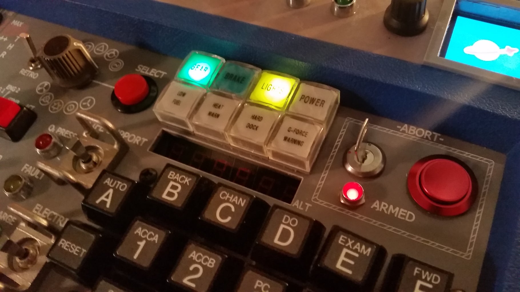
Once the panel is cut I use an acrylic based paint to add extra contrast by painting in the etchings that the laser cutter made. Then I use a scrap piece of acrylic to scrape off the excess paint. this method proved extremely effective. The second picture shows all my components and the panel before final assembly. Simply put you components into the mounting features you designed.
Step 7: Complete Wiring:


Fore wiring projects like this my preferred method is to use primarily female ended multi strand wires. The Arduino also has female connectors. To connect the Arduino to the wires I used double ended male headers. This way I could easily make ribbon cables of specific sizes which helped greatly with wire management.
An important concept to understand for the wiring is the idea of pull up resistors. The Arduino has software enabled pullup resistors available on all digital pins. What this means is that in software you can define a specific digital input to have a pull up resistor. This prevents pins from floating by causing them to default high though a resistor. to activate the pin you simply connect it to ground by closing a switch and the current will take the path of least resistance and go through the button changing the pin state from high to low.
By using internal pull ups wiring becomes extremely simple. Each end of a button or switch simply needs to go to ground and a digital pin on the Arduino. If you plan to use any analog inputs you simply need to setup a voltage divider.
More complex inputs like a button matrix will need additional software. Briefly the 3X5 button matrix works by rapidly cycling which row is high and reading the columns. Using the reading from the columns pins and which row is currently high the button that is pressed can be deduced.
Step 8: Code Your Kerbal Space Program Controller:

How involved your coding will be will depend on which method for communicating to the came and which microcontroller you chose. Here is example code from my first controller (the blue one) which uses the Arduino DUEs Keyboard Library to send signals to the game. Additionally Here is example code for my second controller which used the UnoJoy Firmware to act like a game controller. If you use the UnoJoy firmware any coding will be minimal and inputs only should work out of the firmware install. However remember that you will need to assigns the 'joystick' buttons to functions in the games settings.

Participated in the
Microcontroller Contest 2017


