

Introduction: Arduino Parking Assistant


Those of us who have small garages know the frustration of parking a little bit too far in or a little too far out and not being able to walk around the vehicle. We recently bought a larger vehicle, and it has to be parked perfectly in the garage to walk around the front and back.
To appease my frustration I decided to design a device that would allow me to park in the exact spot every time. I love working with arduinos, leds, sensors, and nearly anything else electronic, so I knew from the start that it would probably end up as a contraption with an Arduino inside and a bunch of LEDs on the front!
I tried my best to document every step of this project well, but please note that it has some complicated, tight soldering; it probably shouldn't be your first project.
Step 1: You Will Need...
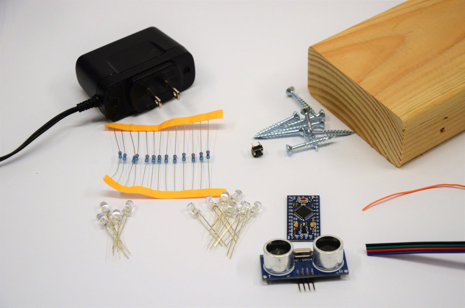


All of these materials are cheap and easily available. I'm not affiliated with any of these suppliers, they're simply where I bought the supplies.
Materials:
- 1x 2x4 - at least 8" long
- 8x Philips Screws - Preferably 1" Long
- 1x Power Supply - 5 volt, 850mA
- 1x Arduino Pro Mini - 5 volt, 16MHz
- 1x HC-SR04 Ultrasonic Distance Sensor
- 12x Through-Hole Resistors - 220 ohm, 1/4 watt
- 8x Green LEDs - 5mm
- 4x Red LEDs - 5mm
- 1x Tactile Pushbutton - 6mm
- 3x Four Conductor Wire Sold by the Foot - 22 gauge
- 1x Stranded Wire - 28 gauge
Tools:
- Wire Stripper
- Bandsaw
- Soldering Iron
- Solder - I use 60/40 Rosin Core
- Hot Glue Gun
- Speed Square
- Stick Glue
- Philips Screwdriver
- Pencil
- Drill
- 7/64" Drill Bit - this depends on the size of your screws
- 3/16" Drill Bit
- 1/4" Drill Bit
- 1" Forstner Bit
- Computer with the Arduino IDE Download Here.
- FTDI Programmer Here
Step 2: Print and Cut!


The first step in this project is to make the enclosure. We're using a technique I wrote about in an earlier Instructable, Easy 2x4 Enclosures.
Print the PDF Pattern included below. Be sure you're set to print at 100% scale.
Now cut out the pattern and glue it to the 2x4. Be careful to line it up with the edges. It's only temporary, so only glue it lightly.
Attachments

Step 3: Cut to Length!


Use your bandsaw to cut the 2x4 along the edge of the pattern. You could also use a chop saw or table saw.
Step 4: Cut the Lid!


Now we need to turn this thing from a 2x4 into a box! Use your speed square to mark a line lengthwise on the side of the 2x4 about a quarter of an inch from the back of the box.
Go back to the bandsaw and cut directly on the line. This will cut a separate piece that will become our lid. You'll be cutting close to your fingers; Please be careful!
Step 5: Bore It Out!


Using your pencil, mark a rough square on the back of the larger block about a half inch from all the edges.
Now use your 1-inch to drill bore out the rectangle. You need to drill as deep as possible without coming through the front. Don't drill too deep!
Step 6: Drill! Drill! Drill!


Chock up your 3/16 inch drill bit and carefully drill each of the holes marked on the front of the pattern. I found it works best if you make a small indention with an awl before you drill.
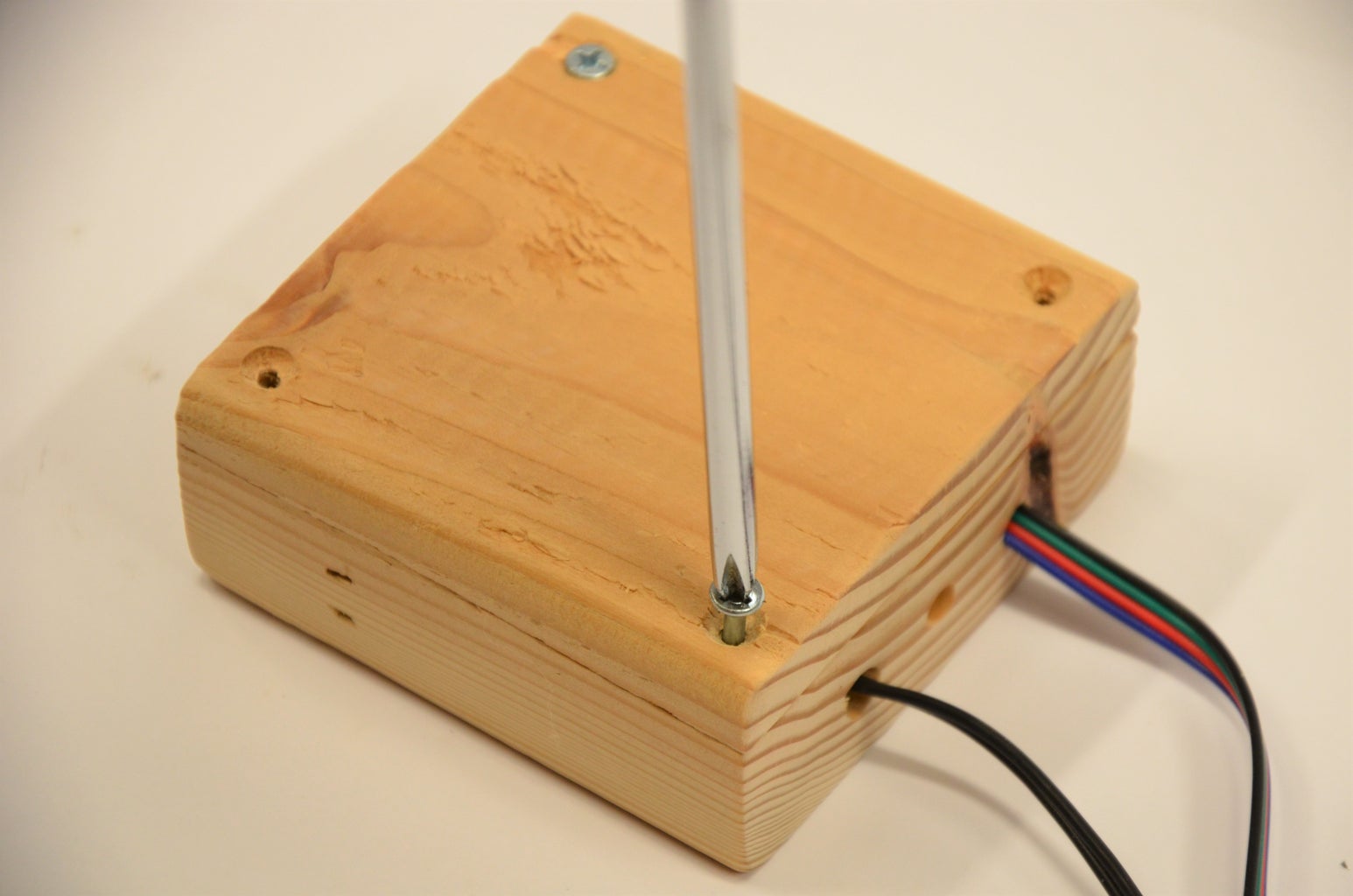
Next drill a 3/16 inch hole roughly in the center of the bottom. This will be the hole for your calibration button.
Now use your 1/4 inch drill bit to drill two more holes in the bottom. These will be holes for the wires.
Step 7: Finish the Control Box!


Now you're using pattern. Peel it off as cleanly as possible.
Take the lid and lay it on the bottom. Turn it around if you have to, you need it in the original orientation.
Next use the 7/64 drill bit to drill a hole about a quarter of an inch from each corner. Drill about a quarter of an inch deep; don't drill through the front!
Use the screwdriver and screws to fasten the lid.
You don't have to, but it makes the box look a whole lot better if you give it a good, through sanding.
Step 8: Insert the LEDs!


It's time to electronicfy this box! (Who says that isn't a word?) The LEDs should be arranged in two rings; a large green ring on the outside with a smaller red ring inside that.
Take a LED and stick it in a hole. Align it so the cathode (shorter lead) is toward the outside. Then put a little hot glue around it!
Repeat this process until all the LEDs are in their holes. Be careful to put the right color in the right hole!
Step 9: Sand the LEDs!


For a more seamless look, sand the LEDs flush with the wood. It works best to sand before the wires are in. (Unlike I did!)
At this point I realized my holes were too big! (I used a size bigger than 3/16")
Wood filler to the rescue!
Step 10: Solder the Grounds!


Bend the shorter lead on a LED and touch it to the short leg on the next LED. Solder these two together and continue around the circle. A needle-nose pliers is a big help!
Step 11: Solder the Resistors!


Cut a short length of wire, about two inches long, and strip it! Twist it around a leg of a resistor, it doesn't matter which end. Use your soldering iron to make the connection permanent! Do this for all your resistors.
Next, grab a resistor-wire pair and carefully solder the free end of it to a LED. Be sure not to let the leads touch any other wires! Do this for each LED, and double-check for shorts.
Finally, solder a short length of wire to the leg that was left when you soldered the grounds.
Step 12: Solder the Button!


Cut and strip another short length of wire, and solder it to one of the button's leads. Then clip all the button's legs off except the one adjacent from your solder joint.
Place the button in the box so you can push it from the outside through the hole. Solder the free lead of the button to the ground connections of the LEDs.
Finally, drizzle a bit of hot glue over the button to keep it in place!
Step 13: Solder to the Arduino!


Solder the pin-headers to the programming port of the Arduino. Then push the two wires (from the power supply and the one for the sensor) through their holes and use a bit of hot glue to keep them from falling out.
Strip the wires from the LEDs and button and solder them to the Arduino according to the wiring diagram above. Below is a printable version of the diagrams for your convenience.
Step 14: Create the Sensor Enclosure!

Now we need to make the enclosure for the distance sensor. I previously wrote about this in another Instructable, so I won't go over that here.
Follow the directions in Easy 2x4 Electronic Enclosures to make the box, then use your 1/4 inch drill bit to drill a small hole in the bottom of the box.
Step 15: Finish the Sensor Connections!


Push the free end of the sensor wire through the hole in the box, then strip it and solder it to the sensor module as in the picture.
- Black goes to GND
- Blue goes to ECHO
- Green goes to TRIG
- Red goes to VCC
Use a bit of hot glue to secure the sensor in the case, then use another dab as stress relief for the cable. Screw the lid on, and you're done!
Step 16: Program the Arduino!


Notice - March 25, 2017: As suggested by commenter "MuchTall" I have updated the code to include an LED countdown during calibration. Please download the new version of the code below.
--------------------------
In order to read the sensor, we need the NewPing library. You can download it here, I also included it below for your convenience. In the Arduino IDE, click on Sketch > Include Library > Add Zip Library... and point it the 'NewPing.zip' folder.
Next, extract the other zip file and open 'ParkingSystemV1.1.ino' in the Arduino IDE. Upload the sketch to the arduino. See this article or this article if you need help.
Screw on the lid, and you are done!

Step 17: Mounting and Use!
Mount the sensor on your garage wall where it can sense a flat surface on your car's bumper, not the grill! Mount the control box higher up where it's visible from inside the vehicle.
Park your car in the best position, and use a long object like a pencil to push the button on the bottom. This will calibrate it. The LEDs will begin lighting one by one to give to you time to move aside. Be sure to give the sensor a clear view to the car! The LEDs will flash green to indicate a successful calibration. Red means it couldn't sense anything within range.
When you drive into your garage, slowly approach the parking assistant; the green LEDs show your distance to the ideal parking spot, red shows you when to stop to park in the perfect position!
--------------------------
I had a lot of fun making this project, and I've found it to be really handy! I'd love to see your versions! Feel free to comment with ideas, thoughts, or even your own version. All feedback is welcome!

Runner Up in the
Microcontroller Contest 2017

Second Prize in the
Sensors Contest 2017

Participated in the
Woodworking Contest 2017


