

Introduction: Visuino: Fingerprint Sensor With Nextion Display


Hi
This time I came up with an hybrid programming project ( traditional Arduino code programming and visuino programming).HMI display are always hectic to program.There are many Display options for adding graphical user interface to Arduino boards. Most of them however require considerable amount of memory, and processing time, and are not suitable for Arduino boards with limited memory, and processing power such as Arduino UNO or Arduino Nano. When the memory is limited, and an advanced user interface is needed, the Smart Programmable Serial Nextion Displays are a popular choice. The Itead offers a free Graphical Nextion Editor for designing the user interface of the display..however process of developing graphical interface for user is simplified by nextion editor.
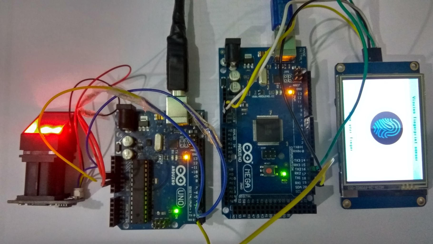
In this project we will be doing seperate programming for Arduino mega controller for nextion display and Arduino Uno fingerprint scanner/sensor R305 and enable serial communication between both the Arduinos.
For nextion display we will use Arduino mega by programming it in visuino and for fingerprint sensor we will use Arduino Uno programmed using traditional method using adaafruit fingerprint library.
We will make an LED on/off using the biometric fingerprint sensor R305.If user fingerprint matches with the fingerprint enrolled with the sensor and it's corresponding user guidance messages will be displayed on the nextion display.
I am very grateful to biaon mitov for developing the advanced visuino software for programming which simplifies the process remarkably.
Step 1: Components


Hardware needed:
- Arduino uno ( or any other arduino microcontroller board)
- Arduino mega
- fingerprint sensor module R305
- Nextion Smart Display(In my case nx3224t028_011)
- Jumper wire
- Led red and 100k resistor.
- Usb type A to B cable
- breadboard
- To program the display you will also need a 5V USB to TTL Serial Converter Module
Softwares needed( All latest versions)
- Arduino IDE 1.6.8 or higher release
- Nextion editor v0.43
- Visuino 7.8.2.102
- Fingerprint windows utility
Step 2: Circuit Schematics

please note:
Arduino uno has used software serial as fingerprint serial data port and used hardware serial port to communicate with Arduino mega.
Arduino mega uses its serial1 hardware port for fingerprint data and serial2 for communicating with Arduino uno.
connections between fingerprint sensor and arduino uno.
- vcc---------vcc
- Gnd-------Gnd
- Tx-----------PIN3
- Rx-----------PIN2
Connection between arduino mega(serial2) and nextion
- vcc-----vcc
- Gnd----Gnd
- Tx2-------Rx
- Rx2-------Tx
connection between uno and mega(serial1)
- Tx------Rx1
- Rx------Tx1
- vcc-----vcc
- Gnd-----Gnd
Step 3: Programming Display Arduino Mega With Visuino


please watch video tutorial for this part.
Attachments

Step 4: Uploading Fingerprint Through Windows Software


Note this step must be done prior to connecting with the arduino uno.
For fingerprint enrollment in sensor i will recommed to connect fingerprint sensor to usb to ttl converter and then connect it to usb port of computer.
Interfacing with Arduino
It is quite easy to use the fingerprint reader with Arduino by using this library from Github. It uses software serial pins to communicate with the reader. The connections should be as follows
connection between usb to TTL and fingerprint sensor :
- vcc------vcc
- Gnd------Gnd
- Tx-------Rx
- Rx------Tx
than open the windows software for enrollment :
- Click Open Device (in the bottom left corner). A new window opens up. Select the COM port used by the USB – serial converter (You can get the COM port from the device manager) and press OK when done.
- You can see the following blue success message and some device statistics such as Baudrate, Package size and Security level in the bottom corner. You can change the baud rate in the bottom left hand corner as well as the security level (how sensitive it is) but we suggest leaving those alone until you have everything running and you want to experiment. They should default to 57600 baud and security level 3 so set them if they’re wrong.
- Now its time to enroll a new finger! Click the Preview checkbox and press the Enroll button next to it (See the red box). Con Enroll means Continuous enroll which you can use if you have many fingers to enroll. When the box comes up enter the ID you want to use. You can use up to 162 ID numbers .
- If the given ID is already used, then the software asks for overwrite. Click Yes for replacing the existing fingerprint. If you do not wish to replace, then click No and give new ID
- You will have to place the finger once again to get a second clean print. Use the same finger.On success you will get a notice.
- If there’s a problem such as a bad print or image you’ll get an error message and have to do it again..
Attachments
Step 5: Programming the Fingerprint Arduino Uno
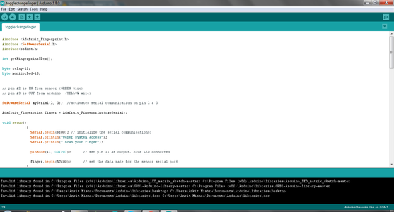


Upload this code to arduino uno after finger enrollment process is over.
then connect fingerprint sensor to arduino uno.
After uploading code open serial terminal in arduino ide to see the instructions for the user.
if they appear it means upto here you are going correct otherwise find the error.
Step 6: Programmming the Nextion Display


Please check my previous instructables if any problem with the display programming part.
you have to simply add txt "t0" component on page0 , futher i have added one more txt component but you can omit.
Note: you must generate font for txt component
txt"t0" component will display fingerprint message and "t1" is for static text.
Make sure same txt have same attributes (check image).
To program the Nextion Display, you will need to Download and Install the Nextion Editor.
Start the Nextion EditorFrom the Menu select |File|New| .
- In the "Save As" dialog, type project file name, and select a location to save the project .
- Click on the "Save" button In the "Settings" dialog, select the Display type (In my case nx3224t028_011)
- Click on the "DISPLAY" tab on the left to show the Display settings
- Select Horizontal orientation for the display Click on the "OK" button to close the dialog .
- open the attached file in nextion editor and compile it , then open build folder and copy the servo tft file and transfer it to sdcard .
- now change solid colour of page to black.
We need to add a text component, and configure it to have 200 characters length.
- In the "Toolbox" on the left click on the "text" component to add it to the design area
- Resize the component to centre of the display .
- In the "Attribute" toolbox, set the value of the "txt_maxl" to 200
- In the "Attribute" toolbox, set the value of the "pco" to 65535 and "bco" to" 0".
To program the Nextion Display with the Nextion Editor you need to connect it with a USB to TTL Serial Converter to your computer or transfer tft file to sdcard.
- Connect the Nextion Wires Connector to the Display
- If your USB to Serial Module is configurable, make sure it is set to provide 5V power
- Connect the Ground Wire from the Nextion Display to the Ground pin of the USB to TTL Serial Converter Module
- Connect the Power (+5V) Wire from the Nextion Display to the Power(VCC/+5V) pin of the USB to TTL Serial Converter Module
- Connect the RX Wire from the Nextion Display to the TX pin of the USB to TTL Serial Converter Module
- Connect the TX Wire from the Nextion Display to the RX pin of the USB to TTL Serial Converter Module
- Connect the USB to TTL Serial Converter Module to the computer with a USB cable .
Attachments
Step 7: Communication Between Arduino
Communication between both arduinos is achieved by connecting arduino uno's Tx pin to serial1 Rx of arduino mega.
you can watch schematics.
Step 8: Playing
Provide power to both the arduinos from same power supply like powerbank to see the live action.
Remember :Gnd pins must be connected to same power supply Gnd.


