The WiFi Duck (no y) is an entirely new project and uses different connections between the Atmega32u4 and ESP8266.
Upload, save and run keystroke injections remotely with an ESP8266 + ATmega32u4
Support me and my projects on Patreon!

- Introduction
- Disclaimer
- Installation
- How to use it
- Improvements
- License
- Sources and additional Links
It's a Wi-Fi controlled BadUSB device to remotely execute Ducky Scripts.
Using a USB device which act as a keyboard to inject keystrokes is well known these days. The USB Rubber Ducky by Hak5 is THE hacker gadget for this kind of attack. It introduced a simple script language called Ducky Script, which this project uses too.
The ESP8266 is a popular Wi-Fi chip used in a lot of projects. Because it's cheap, small and has its own file system (SPIFFS), it's perfect for enabling an easy remote connection and holding Ducky Script payloads.
Although the ESP8266 is awesome, it doesn't have native USB, which means it can't act as a keyboard :(
(cnlohr made a cool project on this and added a USB stack himself: https://github.com/cnlohr/espusb. The problem with that is, that it isn't compatible with the current SDK version, also I wanted to use Arduino to make it more user friendly.)
Here comes the ATmega32u4 into play!
It can act as keyboard and thanks to Seytonic run Ducky Script (link).
So what I did is connecting the ATmega to the ESP8266 via serial.
The ESP will open up a Wi-Fi access point and host a web interface from what you can upload and manage your scripts.
When you hit run, it will send the script to the ATmega, which then will execute it on the target machine.
But why add Wi-Fi ...you might ask.
With Wi-Fi you can upload and run your Ducky Script payloads remotely.
You just need to plug the device in, connect to its Wi-Fi network and you have full control over the target machine.
It also gives you one big advantage over other BadUSBs, you can test your scripts live! You don't need to copy them onto a micro-sd card or compile them. You can run them live over the web interface, which makes its super easy for testing and improving your scripts.
It also adds a lot of possibilities for different attacks.
You could make the target download executables from the Wi-Fi chip, instead of the internet.
Or execute different attacks and send the results back to the Chip. Or open up a reverse shell on the ESP8266s Wi-Fi.
And so on... there are so much possibilities!
Use it only for testing purposes on your own devices!
I don't take any responsibility for what you do with this project.
Upload the arduino_wifi_duck sketch to your ATmega32u4 and upload the esp8266_wifi_duck sketch to your ESP8266.
Then connect the serial pins (RX and TX (Arduino) to TX and RX (ESP8266)) and GND.
What you will need:
- ESP8266 Wi-Fi chip
I recommend using an ESP-12. It's widely used, cheap, tiny and has 4MB of flash memory.
However if you're a beginner you should probably start with a developer board like the NodeMCU or a Wemos d1 mini. - ATmega32u4
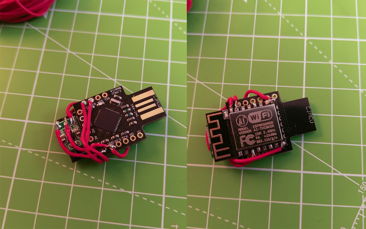
The Arduino Micro and Arduino Leonardo use an ATmega32u4 for example. You could also get a Arduino Pro Micro or other cheap Arduino clones which use the ATmega32u4. I will use an ATmega32u4 CJMCU Beetle. - (a 3.3V regulator)
I put that in brackets because you will only need this if your ATMega32u4 board doesn't provide 3.3V. The ESP8266 only works with 3.3V, so depending on your board you may need a regulator to get 3.3V out of the 5V. - Some skill, knowledge and common sense on this topic
That's probably the most important part here. This project is not noob friendly! If you are a beginner, please start with other projects and get some knowledge about how Arduino and its code works, how to handle errors and how to work with the ESP8266. I can't cover every little detail here. Please respect that. Depending on your hardware choices you may need to add or change a bit of the Arduino code.
So make your hardware choices!
Also I wouldn't go straight forward and solder everything together. Test it beforehand, otherwise debugging can be hard!
For an easy start, better debugging, further development or if you just wanna test this project, I recommend using a Nodemcu + an Arduino Leonardo:
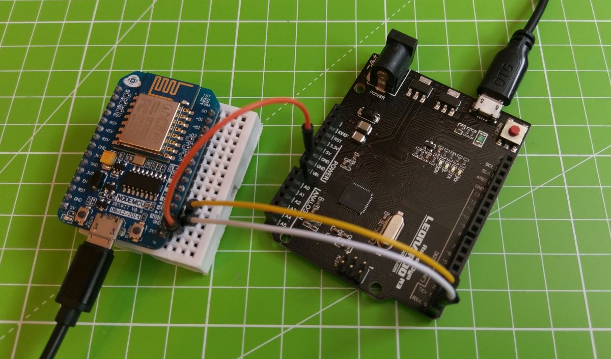 This is easy to setup, you don't need any soldering skills and you can still use both the NodeMCU and the Arduino for other cool projects.
But now let's get started!
First you will need to flash your ESP8266.
You can either flash the bin file directly or compile it yourself using Arduino.
Note: You will only need to flash it once, every new update can then be done over the possibilities.
If don't use a USB dev board and don't know how to flash your plain ESP8266, I recommend you to have a look at this instructable: http://www.instructables.com/id/Getting-Started-with-the-ESP8266-ESP-12/?ALLSTEPS
You could also use your Arduino to flash it: https://gist.github.com/spacehuhn/b2b7d897550bc07b26da8464fa7f4b36 (The connections are the same for this project, the only difference is that you need to set GPIO-0 to LOW to enabling a firmware update).
Flash the .bin File
Go to releases and download the right bin file for your ESP8266.
You can flash it with the esptool or the nodemcu-flasher.
Upload using Arduino
Open the esp8266_wifi_duck sketch with Arduino.
You need to install the following libraries:
Then compile and upload it to your ESP8266 (check if your settings are right).
Open the arduino_wifi_duck sketch in Arduino and upload it to your Arduino.
Ok so now you need to connect the ESP8266 with the Arduino.
Connect these pins:
| Arduino | ESP82666 |
|---|---|
| TX | RX |
| RX | TX |
| GND | GND |
| VCC (3.3V) | VCC (3.3V) |
Like I mentioned before, you'll need a 3.3V regulator if your Arduino only provides 5V.
Don't connect the ESP8266 to 5V!
If you use a plain ESP-12 like me, you also have to set the enable pin and to HIGH and GPIO15 to LOW:
| PIN | Mode |
|---|---|
| GPIO15 | LOW (GND) |
| CH_PD (EN) | HIGH (3.3V) |
Once you flashed the software, you can update it over the web interface.
Go to 192.168.4.1/update and upload the new .bin file.
(In Arduino go to Sketch->Export compiled Binary to compile your own .bin file)
Plug your Wi-Fi Ducky in and connect to the new Wi-Fi network WiFi Duck. The password is quackquack.
Open your browser and go to 192.168.4.1.
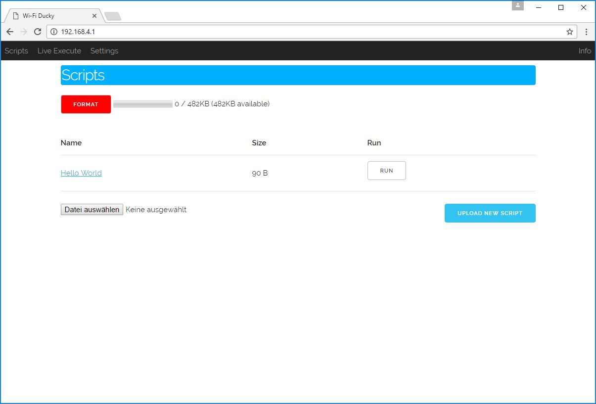
There you can now upload, view, delete and run new Ducky Scripts.
PLEASE NOTE that the max length per row for a script is 600 chars.
How to write Ducky Scripts: https://github.com/hak5darren/USB-Rubber-Ducky/wiki/Duckyscript
Happy hacking :)
My wishlist:
- add support for Digispark (ATtiny85) as alternative for the ATmega32u4 Arduino
- change settings within the web interface (Wi-Fi SSID, password etc.)
- full support of all Ducky Script commands (DEFAULTDELAY is missing)
- auto execute scripts
- add mouse
- control over the internet
This project is licensed under the MIT License - see the license file file for details
The USB Rubber Ducky: https://hakshop.com/products/usb-rubber-ducky-deluxe
The Malduino (a BadUSB-Arduino/Rubber-Ducky-alternative by Seytonic): https://www.indiegogo.com/projects/malduino-badusb-arduino-usb#/
Seytonic: http://youtube.com/seytonic https://github.com/seytonic
Arduino Ducky Script interpreter: https://github.com/Seytonic/Duckduino-microSD
Cnlohrs ESP8266 USB Software Driver: https://github.com/cnlohr/espusb