

Introduction: Minimal Arduino UNO (a.k.a. Arduino Pro)


Hello everyone! In this Instructable, I'll go through the process of making a minimal Arduino Uno compatible board with can be programmed using any usb-uart converters(e.g. FTDI board). The complete board may or may not be a cheaper solution, depending on where you buy your stuff. For me, it took less than Rs.200 (~$3).
Here I'll use simple and quick toner transfer method to create the PCB. While using tools like saw and box cutter to carve out the shape. The board itself is almost 90% compatible with the original Uno.. a few pins are missing which I'll go through in the following step.
So, Let's get started..
Attachments

Step 1: Tools Required.
- Soldering Station.
Although you can use cheaper irons but a good quality soldering station is recommended if you're into electronics.
- Ferric Chloride.
For the etching process
- Laser printer.
I'm using Canon MF4720w printer, But any good quality Laser printer will do the job.
- Steel wool.
For cleaning the PCB
- Cloths iron.
Use any iron and set the temperature setting to maximum
- Safetly gloves and Eye protection.
Ferric chloride can be very toxic. Reasonable precaution should be taken while handling such chemicals.
- Saw and box cutter.
For the cutting the PCB to size.
- A computer.
Well.. Duh
Step 2: Components Required.
- Copper clad board
Here, only single sided board is required. But you can go ahead and make a double sided one.
- Atmega328p-pu with IC base
Not that it's not 328-pu. it should be 328p-pu
- female headers
8-pin x2
6-pin x2
10-pin x1
- 3x2 male ISP header
for burning the bootloader
- 16mhz crystal
- Some jumper cables
- 4x 3mm LEDs
select color according to your needs
- 5x 0.1uf 0603 Capacitors
- 2x 22pf 1206 capacitors
- MCP1700T 3.3v reglator
I used this because I have several of these laying around. You can use LM1117, but you'll have to modify the circuit accordingly.
- 4x 470e 0603 resistors
- 2x 1k 0603 resistors
- 1x 10k 0603 resistors
- A DC jack
optional
- MCP1703 5v requlator
optional! if you're not using a dc jack, then this is not required.
Step 3: Designing the Circuit.
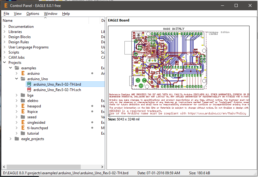
As I mentioned in the Intro, It's based on the arduino Uno board. So the first thing we'll do is to go to THIS website to download the source PCB file from the website.
download the eagle files as shown in the following picture. 
Extract and copy the folder to your eagle projects directory. by default, it's located as $USER$\documents\eagle\
Now open up EagleCAD and navigate as follows.
Open the *.sch file and you'll be presented with the following window

Now start removing stuff and only leave the atmega328p IC the female headers and the ISP header. After that, start adding components as shown in the following picture.

The board has a few pins that are not populated... i.e. AREF, IOREF, SDA/SCL pins along side digital pin 13 (but you can always use pins A4 and A5 if you want to use i2C) .
You can also download the PCB file already compiled, from the first step. Now that we've created our schematics. Let's move on to creating the actual PCB layout.
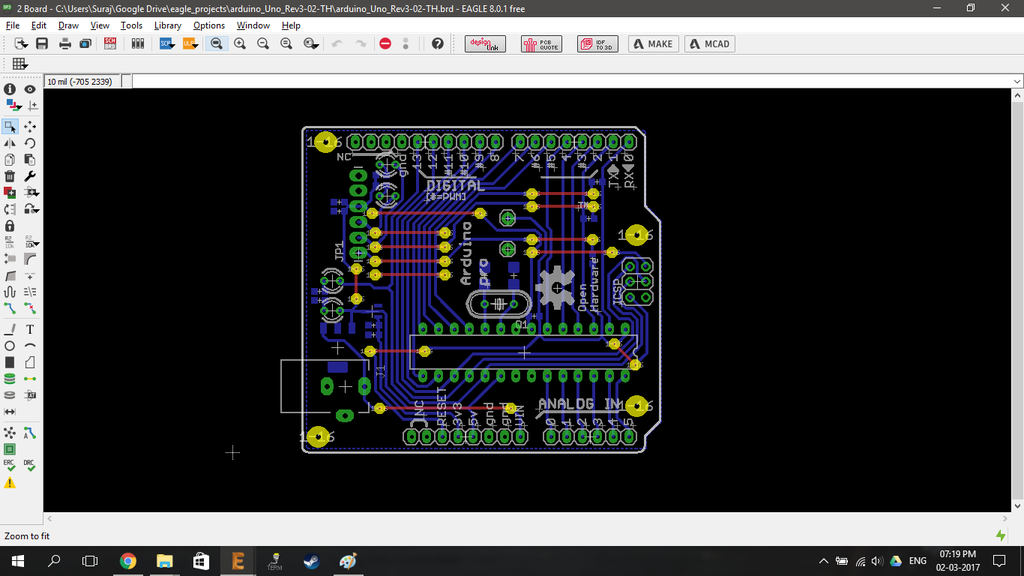
Step 4: Designing the PCB Layout.
After we removed all un-necessary components from the original file, We'll get a PCB layout as follows.

After adding the required components layout according to the following
As stated in the previous step, You can download this file from the first step.
Step 5: Printing the PCB Layout
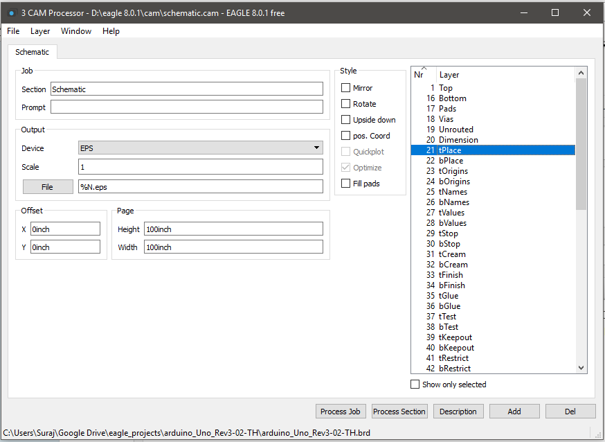
Switch to the Board layout window in EagleCAD and click "CAM processor". A new window will open.
Now, from "File" menu click open>Job. and select "schematics.cam" file from the dialog. After that, click "process job" on the bottom of the "CAM processor" window. Close everything up and open the folder where youe eagle schematics and board files are stored.
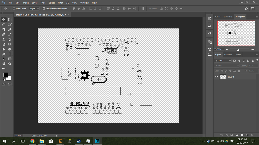
You'll notice that a new *.eps file is created. Open that file using photoshop. you'll be greeted with the following window(Photoshop CC 2017)

Click open and following window will appear.

NOTE: Since this is a bottom layer PCB, it doesn't need to be mirrored before printing.
Now print this file on a glossy side of the paper. and prepare for the PCB printing and etching procedure.
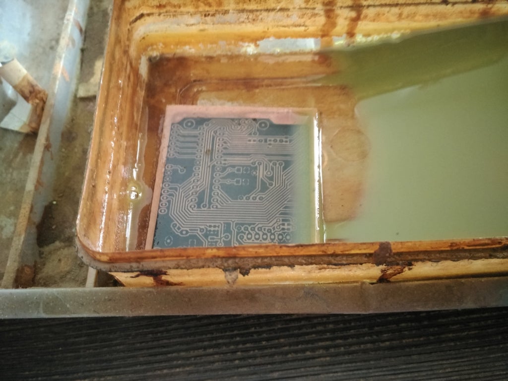
Step 6: Printing the Layout on the Copper Clad Board.
Here, I'll be using the popular toner transfer method. You can easily good tutorials for it... there are literally thousands of tutorials available on youtube , instructables and other websites. So there's no point in showing yet another tutorial.. But here's the pcb in etching process.
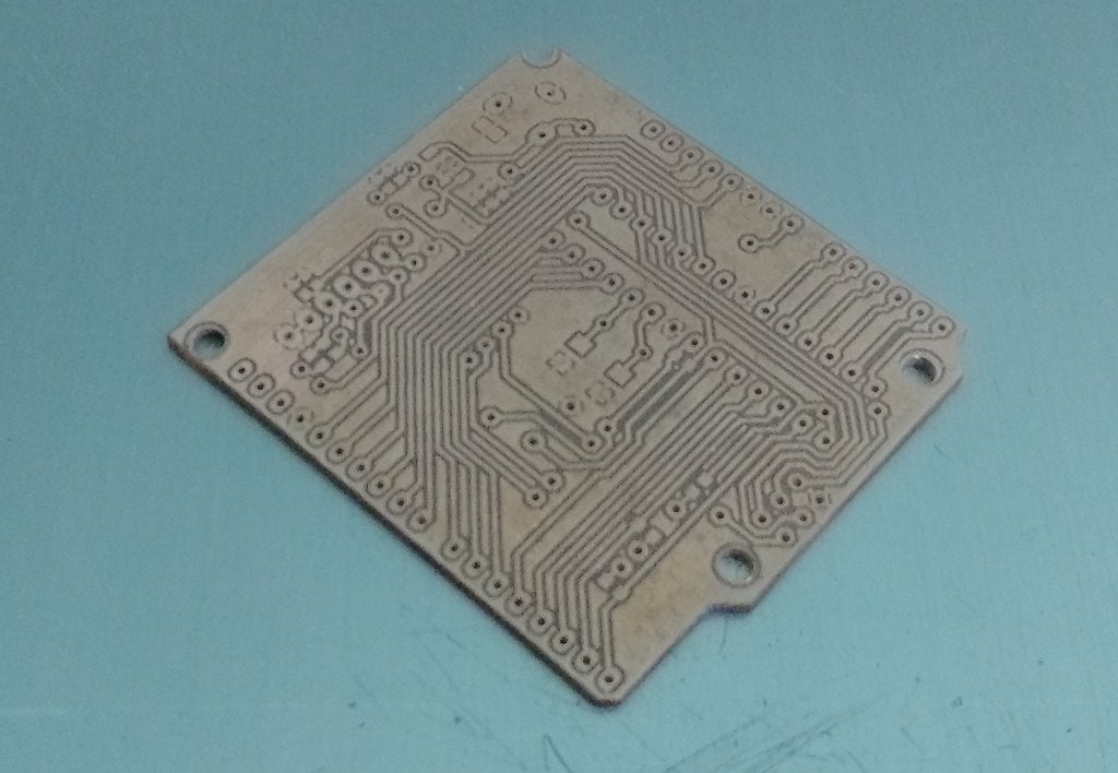
After etching, Cutting and drilling holes. the PCB looks like this.
Step 7: Printing and Transfer of Top Layer Silk Screen(sort Of)
It's time to open EagleCAD again. Open the arduino uno project, switch to board layout and click on "CAM processor". Once again, open schmatics.cam file in the cam processor. But this time, from the layers list on the right side of the window, select only "tPlace" and "tName" and deselect all others. just like follows.
Click "process job". And open the same *.eps file in the project folder using photoshop. And then mirror it so that it looks like as follows.
Now print this file. Again on glossy paper. Align the print on the top layer of the previously etched PCB. and use same toner transfer method to transfer top silkscreen toner to the pcb. It should look like the following.
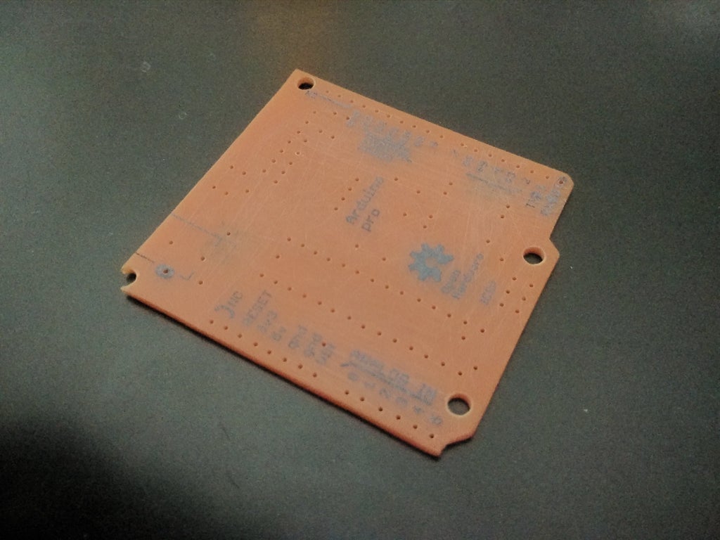
Note that it's not clearly visible. So later i added a drop of super glue to make it more clear to see the text.(you can see in the Thumbnail of the project.)
Step 8: Soldering.
Now begins the soldering process.

The components can be seen from the schematics and pcb layout that I've attached in the intro.
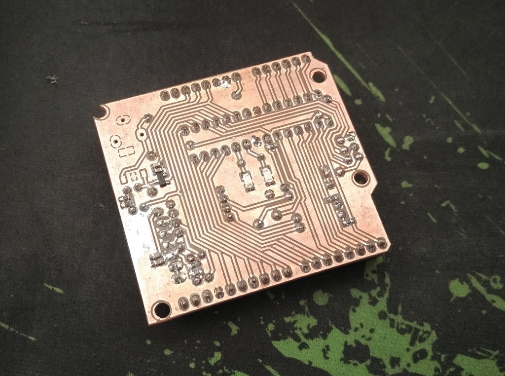
After the Soldering process it'll (hopefully) look like this.

And the bottom layer looks like this.
Step 9: Burning the Bootloader.
The chip I bought had the bootloader preinstalled but you can easily burn it yourself using an AVR programmer or an arduino using the 6-pin ISP header. You can do this from the Arduino's IDE itself.
Step 10: Finish
Thanks for your time.
please leave a comment if you liked the project. or if you may have noticed any mistake.
Have a nice day.

Participated in the
Microcontroller Contest 2017


