

Introduction: Arduino Nixie Clock for Absolute Beginners


***Special note**** Working on a multi-video youtube video guide, I will post the link once its done.
Some you tube videos are up, still working on more:
Link here: https://www.youtube.com/watch?v=MODVkeMj4jg&list=PLpv9lTQHOytlEZIFrcOy_TBMV8cIuZtJM
This is my first instructable so please feel free to comment on anything related to this project.
An overall synopsis for this project is an arduino based nixie clock that runs on a ds1307 break out board, a voltage step up chip, the arduino uno, and 14 in nixie tubes. I will try to stay away from the case that I built because I am fortunate enough to work in a shop that has professional CAD programs as well as million dollar fiber optic laser and half million hydraulic press brakes, which most people do not have access too.
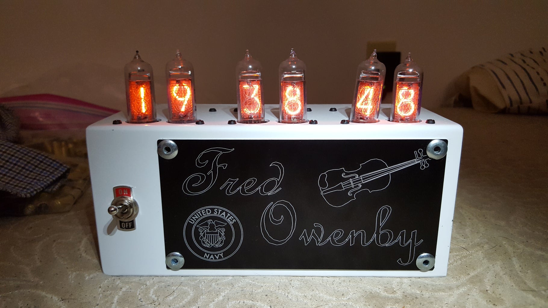
This project was a gift for my great-grandfather and I did include a picture of the final product.
Step 1: Parts List


Please note before you get started on this project it will cost about $130 in parts and probably a little more if you want quality and good looking components.
Parts List (Really the must have components):
- Arduino Uno - $16 - On Amazon Here
- ds1307 clock breakout board - $16 - On Amazon Here
- Arduino Uno Prototype shield - $12 - On Amazon Here
- .1 uF capacitors (qty 6) - $4 - On Amazon Here
- 15K resistor (qty 6) - $4 - On Amazon Here
- Nixie Tube Drive IC Chip (qty 6) - $14 - On Ebay Here
- Shift Register IC Chip (qty 3) - $9 - On Amazon Here
- 14 in Nixie Tube (qty 6) - $25 - $35 - On Ebay Here
- 12V DC 2.5 amp power supply - $10 - On Amazon Here
- Voltage Step Up Chip - $17 - On Ebay Here
- On/Off toggle switch - $13 - On Amazon Here
- 16 pin IC socket (qty 9) - $10 - On Amazon Here
- Electrical connectors, I used a basic male and female ends, they can be found at hardware stores or the web
- Some type of PCB to solder everything too, (*see details below.*)
The PCB is a component that can be done in a few different ways here. You can make an ugly one or design and build one. I personally designed a board in a software called Eagle and then exported it into a zip file that I sent to a company called OHS park online. They built and shipped my custom board to me for $23. Anyone can buy the same board I designed which would run perfectly with the code I have uploaded to this instructable. The link to this board can be found here. Anyone can order my board project from OHS park.
===================================================================================
After you have gathered all your parts and soldered together any of the purchased boards you are ready to continue to step 2.
Step 2: Setting Up the Wall Outlet and Step Up Chip


Setting up the wall outlet
There are plenty of wall outlet DC converters all over the place. I will focus on how to use the one I included in the parts list. If you use a different wall outlet than the one I used make sure it meets the same 12V DC and 2.5 Amps requirements.
The first thing is to get too bare wire from the outlet. For the one I am using you will take one of the female multiple tail ends and cut off one of the female ends close to the end of the base. From there you will see two wires inside of the single black insulation rubber. One is red and one is black. The red wire is the "hot" wire and the black wire is the "ground" wire, abbreviated as "GND." Use a pair of wire strippers to expose about two inches of the black and red wire. After that strip about a half inch off each of the red and black wire to expose the bare copper.
After you have added a connector to each end of the power supply you will need to cut two lengths of solid core wire. I strongly suggest you use a red and black wire for this. Cut a length of red and black solid core wire that is about 5 inches long and strip both ends of the solid core wire. On one end of the solid core wire, crimp or add another wire connector that will attach to the wire connector at the end of the wall power supply. Connect the two wire connectors so you have a solid core end for both the hot and ground wires. Leave one end of the solid core wire striped to be used during the project.
After you have connected the wire be sure to add heat shrink or electrical tape around each wire connection so that you can not have any metal on metal contact. I usually use electrical tape so that it is easy to get back to the connection for any kind of trouble shooting. For a better looking final product you can use heat shrink. You can also solder the wires into the wire connectors for added contact surface at the connection. I even solder the connectors together.
Setting up the step up chip
There are many nixie power supply chips on the market but I will focus on the one I added to the parts list in section 1. The step up chip should be the first portion of this project because it will be necessary to test your nixie tubes individually as well as in conjunction with the other portions of the project.
This step up chip has input and output terminals. The step up chip I chose for this project comes with some soldering required, so go ahead and solder the parts onto the PCB. You will need to add power to the chip's input and then measure the output with a multi-meter. You can then raise or lower the output voltage by adjusting a block that is on the step up chip.You can either use a bench power supply, or the wall power supply I put in the parts list. Please note if you use the variable power supply you will eventually want to re-measure and fine tune the terminal block with the wall supply since this is what will be used on the final clock. The wall supply may be slightly different than a bench or variable power supply.
DO NOT TOUCH BOTH THE BLACK AND RED WIRE AT THE SAME TIME OR BOTH OF THE TERMINALS AT THE SAME TIME WHILE THE POWER SUPPLY IS SENDING ELECTRICITY!
WARNING: HIGH VOLTAGE: UP TOO 210 VOLTS!!!! USE CAUTION AND DO NOT TOUCH A HOT AND GROUND TERMINAL AT THE SAME TIME!
------Using wall power supply
Step 1:
On the portion of the wall supply that has multiple ends, all barrel jacks (female), cut off a female end right at the base. From there strip off the black insulation rubber. This will reveal two wires, one red, and one black. The black wire is the ground wire and the red wire is the hot wire. Strip the end of each of these wires off as well to expose bare copper metal.
Step 2:
Get two electrical connector and attach one to each end of the bare metal. I prefer shovels and clip style connectors that must be crimped onto the wire. I usually also add some solder to where the copper wire meets the electrical connector. Go ahead and attach an electrical connector to both the hot and ground wire.
Step 3:
You will now want too get two pieces solid core wire. Most arduino enthusiast have it in large rolls. You will want solid core wire to minimize having to braid the copper strands over and over again. I HIGHLY SUGGEST you use a red and black wire to match the wires in the wall power supply. Strip a small amount off each end to expose bare metal. You will want to attach an electrical connector to one end of each of your two wires. Once again I usually put a little solder on each connector for better surface contact. Make sure you attach an electrical connector that will connect to the connectors you used on the wall power supply.
Step 4:
Once you have the electrical connectors on both the two wires on the wall power supply as well as the two solid core wires go ahead and plug them into each other. Make sure you have good contact between the connectors. You can use most multi-meters to check this,
Step 5:
After you have everything connected together go ahead and plug your wall power supply into an outlet. Be sure not to let the black and red wires cross or you will cause a short which can easily damage components or generate enough heat to cause a fire. Check to make sure you have at least 12 volts coming from the wall outlet power supply.
Step 6:
Once you are sure you have a solid 12 volts DC current coming from the wall power supply, go ahead and use heat shrink or electrical tape to first tape each individual connection, one for the hot wire and one for the ground wire, and then tape both of the taped portions together. This electrical tape or heat shrink will keep your metal contacts from shorting out while your doing other stuff.
Step 7:
Now you will need to plug the wall power supply into your step up chip. Remember the step up chip has a side for 12 volts in and an output with a range of much higher voltage. The input side of the step up chip will be marked with a "GND" or ground, and a hot wire input. Plug each wire into their respective terminal spot.
Step 8:
I recommend you get a friend for this step. You will need to have someone hold the probes of the multi-meter on the output terminal so you can get a reading of how many volts is coming out of the step up chip. You will then need to adjust the output voltage by using a small screw driver to turn the variable block on the step up chip. You want to get an output voltage of about 178V - 182V. Once this is set you are all done and your step up chip is ready.
-----Using variable power supply or bench supply
If you have a variable power supply go ahead and set it up to 12 volts and set the amps to a minimum that will allot for 12 volts. From there, connect the ground and hot wire to the corresponding terminals that are marked as the 12 volt input, and then measure the output voltage. Set the terminal block to the required output voltage. I used 178 volts for my clock.
------------------------------------------------------------------------------------------------------------------------------------------------------
Once you have the step up chip set to the required voltage you will be ready to begin testing your tubes individually.
Step 3: Testing Each Individual Nixie Tube


Before moving on with the build it is a good idea to test each nixie tube at each leg to make sure it is working. Make sure to check all the cathode legs connected to a numeric digit. Be mindful that two of the cathode legs that are adjacent to the anode are decimal points inside the tube. These have a much smaller required amperage level and can be blown out if they are given too high of a load.
To test each digit you will have to set up a simple circuit, much like a light bulb, and ground out each cathode leg (any leg that connects to a numeric digit). You will want to run your power supply (or wall plug in) into your step up chip just like you did when you were setting up the voltage for the step up chip. From your voltage step up chip you will run a wire from your positive terminal into a bread board, then in series a resistor (15k to 25k is fine), and from there run a male to female jumper wire from the resistor to your nixie tube anode leg (the positive leg). it will be important for this wire to hold onto the nixie tube anode leg by itself because you will need both hands free to the other portion of this test. The positive leg is the leg that is in the very back of the tube. It has a white ceramic piece inside the tube just above where the wire is exposed.
INJURY WARNING: PLEASE NOTE THAT THIS IS ABOUT 170 VOLTS. BE CAREFUL NOT TO TOUCH THE GROUND AND HOT WIRE AT THE SAME TIME!
Once you have the positive anode side of the nixie tube set up, plug a jumper wire into the ground terminal on the high voltage side of your step up chip and leave the other end unconnected. Now carefully hold the nixie tube in one hand and touch the ground wire running from the voltage step up chip to each numeric digit leg of the nixie tube. Remember not to touch the ground wire to either the decimal legs or the anode leg (the one hooked into the positive side of the power supply). As you move around the tube you should see each number light up. Once you have tested all the digits this step is done.
Step 4: Figuring Out Your Shift Register


One of the two IC chips that is used in this project is the shift register. This chip will drive two 74141 nixie IC chips so its important to understand how these work. The chip is essentially a way to expand IO ports on an arduino controller, but here it is being used to drive the nixie tube control chips. You will use one for hours, one for minutes, and one for seconds, three chips in total. There is a really great instructable on how to use a shift register here. You will need to use the shift register to send high and low signals to the IC chip to control the nixie tubes.
The best way to visualize this is that you will control each of the 74141 chips with 4 inputs and you can equate each of those inputs with a light coming from the shift register. If the light is turned on then that pin is sending a high signal and if it is dim then the signal is low. Considering there are 4 inputs on each chip and there are two chips that means a total of 8 lights so the shift register is a really clean way to run these tubes.
Special thanks to codebender_cc for his instructable.
Step 5: Understanding and Testing One 74141 Chip With LEDs' and the Nixie Tubes


The next place to turn on this project is understand and testing the nixie tubes in conjunction with the 74141 IC chip. The nixie tube can be confusing to a new arduino and electronic builder, so I built a test circuit with LEDs' and then replaced the LEDs' with a single nixie tube. This way you don't have to worry about any issues with the tube and don't have to worry about including a 175 volts power supply. You can run the LEDs' with the arduino power.
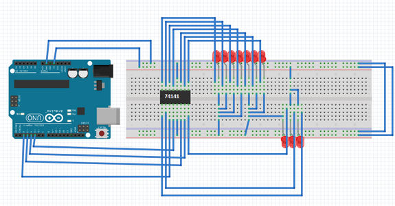
There is a great instructable on driving a single nixie tube with an arduino uno and a 74141 IC chip. You can find this instructable here. To test with LEDs' use either 5 volt rated LEDs' or standard LEDs' with a resistor in series. Where ever you see a nixie tube cathode, or connection to the 74141 IC chip, attach a ground end of an LED and then run the other end to a positive power terminal. Of course use a resistor as needed. When you run the code to begin manipulating the nixie tube, a single LED should light up to the corresponding number on the 74141 IC chip. ie. Every time the 0 digit is supposed to be displayed on the nixie tube, the LED on the corresponding 74141 IC pin should light up. So each LED represents a single digit. You can find a chart of the 74141 IC chip's outputs. Try writing a code that will light up the digits 0 to 9 with a second or so delay between each digit. Looking at my picture schematic (fritz) instead of wiring all the LEDs in on the right side of the breadboard you can run them between the chip and the power bar on the breadboard.
Once you have this concept replace the LEDs' with a single nixie tube. Use the circular chart in the pictures of this section to see which leg of the nixie tube corresponds to which pin of the 74141 chip. After replacing the LEDs' with the nixie tube be sure to wire in the voltage step up chip to power the nixie tube. DO NOT forget the anode resistor on the nixie tube and be sure to use a strong resistor if your using the wall power supply because it will send a large amp load to the nixie tube and can damage it. If you are using a bench power supply just slowly raise the volts and amperage to 12 volts while supplying the lowest amperage possible. Otherwise start with at least a 25k ohm resistor and adjust resistance from there. You want to have a nice orange and yellow glow. If there is a lot of violet, blue, and purple coming out in the tube, then it is running too hot and you need to increase the value of the anode resistor. If the digit is not fully lit then you need to lower the resistance of the anode resistor. Once again try and write some code that will count from digits 0 to 9 with a second or so delay between each digit.
After You can successfully run a single nixie tube with a 74141 chip it will be time to merge the shift register and two 74141 IC chips to build a two tube platform with a single shift register driving two 74141 IC chips. This means a single shift register will drive two individual tubes, and with three sets of this circuit, we will make a seconds, hours, and minuets board
Special Thanks to Proto G for his code and instructable I used for this portion of my instructable and on my final clock!
Attachments

Step 6: Building and Testing a Dual Tube Circuit


After figuring out and testing the both the shift register chip and the 74141 IC chip it is time to integrate them together. In the previous step I suggested using LEDs' instead of the actual nixie tube to remove the power supply and tube portions of the circuit to make trouble shooting easier, the same goes with this step. Since you will be running a circuit with two 74141 chips you will need 10 LEDs' to test the circuit.
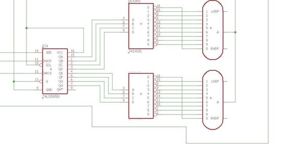
Set up the circuit as shown in the pictures for this step and replace the nixie tube cathodes with LEDs'. Attach a ground leg of the LED to each pin of the 74141 IC chip pin leg that displays a nixie tube digit. Hook the other side of the LED to a power bar on a breadboard. Connect the shift register to the 74141 IC chips as shown in the schematic in the picture of this step. Again, try and count from digits 0 to 9 with a second or so delay between each digit.
Once you have both of the tubes functioning and count from digits 0 to 9 with a second or so delay between each digit it will be time to introduce the ds1307 time breakout board and actually make each time unit appear. This mean that depending on which 3 inputs from the arduino pins you change out you should be able to switch between seconds, minutes, and hours.
UPON REQUEST Kille1992. I have added the full schematic and eagle files for the PCB.
-The autocad EAGLE file is called shiftNixie.brd
-The schematic file is called shift nixie.sch
-The zip folder includes the two filed that are stand alone. The misc. other files in the zip folder are for generating a board with the OSH park company.
Step 7: Understanding and Using the Ds1307 Breakout


**SPECIAL NOTE** I have realized from issues people were having in the comments section that if you have a battery in your RTC and need to set the time you must change the time assign code. The change is simply removing the "!" character in the line "if (! rtc.isrunning()) {"...........By changing this to "if ( rtc.isrunning()) {" your clock should change the time.
After you have the tubes working and can manipulate the digit output on each tube it is time to add the time aspect to the project. The ds1307 breakout is what I used for this clock and will cover for the tutorial. The hardest part of this is getting each digit individually and then getting the tube to display the proper digit. But before all this, it is important to understand how to simply read time and get it to display with the ds1307.
First you should read adafruit's learn page on this breakout board which can be found here. Please note that on the left hand side of the page you can see a blue hyperlink list that includes: What is an RTC?, Parts List, Assembly, Arduino Library, Wiring It Up, Understanding the Code, and Downloads. Going through all these hyper links and reading up will greatly increase your understanding of what this chip is, what it does, and how it works.
Next you will need to download and install some libraries. You will need all of the following libraries: The RTClib library, the RealTimeClockDS1307 library, and the wire library. The wire library should already be installed on the arduino software. To install a library download the .zip file from git hub, renamed the library removing the "master" portion of the key name and then move the folder to the library folder in your arduino program files. There are a lot of tutorials on how to do this that you can find online if you google search it.
*PLEASE NOTE. For my fritz schematic I used the spark fun ds1307 (red) instead of adafruits, because the fritz library does not have adafruit's ds1307. The pins are the same though. Also note, you can plug the ds1307 directly into the arduino uno and set the A3 and A4 pin to high and low for power.
After installing the libraries you can open some examples from the library folders to look over code and figure out how it works. I feel like the best example is at C:\Program Files (x86)\Arduino\libraries\RTClib\examples\ds1307. Open the arduino sketch ds1307 and follow the code, it is fairly self explanatory. You will want to copy and paste bits of code into a new sketch and then use your comm port to make sure the time is coming out correctly. Once you can correctly print the time inside of the comm port on your screen you will be ready to move on to the next step.
Attachments
Step 8: Running One Set of Nixie Tubes With the DS1307
This step will go over how to actually use the DS1307 and convert each digit into a digit on each tube. Once again instead of using the nixie tube you can use LEDs but by now you should be pretty comfortable using the tubes. This circuit will look exactly like the step where you counted down on a nixie tube with a shift register. However the code will be the focus on this step. You will need to use code to convert the time from the DS1307 breakout board to read each time digit and display it on the tube.
Considering each set of tubes will use 3 output pins from the arduino, the best way is too have 3 output pins beside each other for each unit of time. For example, pins 2,3, and 4 will control seconds, pins 5,6 and 7 will control minutes, and pins 8,9, and 10 will control hours.
Please note that every so often the tubes will need to go through an anti-poisoning cycle. Essentially, if a tube has a single digit on for long periods of time and the other digits are never used it can cause the tube to go bad. This is especially true for the tens digit on the hours tube since it will only use at max 3 digits (if you are using military time). Considering the tens digit on the hour tube will only change once every 12 or 10 hours it is important to cycle this tube every so often to increase the life span of the tube. I like to use this time to make a cool or unique event to happen. Just make sure whatever you end up programming cycles through all the digits of the tube. I have all the tubes count down from 9 with a couple second delay but you could program whatever you wanted.
The best way to test this portion of the build is to take one set of tubes and plug them into each set of output pins on the arduino and test each time unit. Once every single one of them works then you are ready for final assembly.
Attachments
Step 9: Final Assembly


Once you have each unit of time working you will be ready for final assembly. There are some very important steps here that you will need to take and depending on how you do it will make your maintenance of this clock much easier or harder.
Soldering Up The Prototype Shield:
The most important to consider here is the prototype shield for the arduino uno. You have a GND and 5V row on the prototype shield and you can run all of your 5v logic and ground from these rows. You can either solder the wires straight into the rows, or preferably, solder in pin headers (female) and stick the 5V and GND wires into them. I would highly recommend soldering in the headers or else you will have to un-solder any of the wires that you put into the board if you need to trouble shoot something.
You will also need to solder in 4 pin heads for the high voltage wire and a row of 5 pin heads for the high voltage ground, please note that all grounds are common. You will need to tie all of these pin heads together with solder on the bottom of the proto board.
Lastly, you will need to add the DS-1307 breakout boards to pins A2 to A5. Remember to point the breakout board into the proto board and leave the last pin hanging off the side so that it is not inserted into anything.
Dual Tube Circuits to Arduino:
At this point you should have three circuits with two tubes on each. Each circuit will have the following: 2 anode resistors for the tubes, 2 Nixie Tubes, 2 IC chips to run each tube (74141 chip), and 1 shift register running the two 74141 IC chips. You will have the following inputs: 1 high voltage positive wire, 1 high voltage ground wire, 1 red 5v logic wire, 1 black 5v logic ground wire, and 3 other wires that will be use to control the shift register.
Plug your high voltage red wires into the row of female headers you soldered on too the proto board. Plug your high voltage ground wires into the female headers you soldered into the proto board. Plug the 5v red logic wires into your proto board. Plug the 5v ground wires into your soldered on female headers.
The last step is to plug in your data wires that control your shift register. Arduino digital pins 2, 3, and 4 will control the seconds. Arduino digital pins 5, 6, and 7 will control the hours circuit. Arduino digital pins 8, 9, and 10 will control the minutes. Please view the schematic from the step that was used to show how to drive two 74141 IC chips with a shift register to see the schematic.
On/Off switch
There are two main ways you can wire in your on/off switch.
Method 1: Wire the on/off switch between the wall power supply and everything else.
This method will turn the entire circuit off when the switch is set to the off position. To use this method simply use electrical connectors to place the on/off switch between the wall power supply and both the step up chip and the Arduino proto board. You will run the red 12v wire into the switch and then have two wires coming out of the toggle switch into both the step up chip as well as the Arduino proto shield. The pros to this set up is that your shift register and Arduino will not be running all the time and will extend the life of your IC chips. The cons to this is that you will have to rely on the battery for to keep the time on your DS-1307 breakout board. However, the battery and board are rated for a 7 year lifespan with before battery replacement.
Method 2 (My method):
I decided to run the on/off switch between the wall power supply and the step up chip. This way the arduino stays on all the time and I just turn the tubes on and off. Of all the components that will go bad the first thing will most likely be the tubes. This will keep the battery of the DS-1307 alive longer and since it was built for an older gentlemen who could not trouble shoot this stuff on his own I wanted to maximize the time it would keep time without any maintenance.
Power Supply:
You will need to hook up your external wall power supply as well. This is done by splitting the end of the wall supply at two points, you already did this at one. This will leave you with two sets of a red and black wire at 12 volts. Run one set of wires ( a red and black one) to the voltage step up chip, and another set to the arduino board. Plug the red (12V wire) into the Vin of the arduino board and the black wire (GND) into the GND pin on the arduino shield. Note the arduino board can handle 12V, so don't worry about hurting the board with the wall power supply. However, DO NOT RUN THE ARDUINO IN SERIES AFTER THE STEP UP CHIP! This will most likely fry the arduino faster than you can smell it burning.
Please note: you can always solder the wires directly into the proto board but this will be a huge pain later if you have to disconnect any wires, it is much easier to pull them out of pin headers than to remove solder.
Step 10: Case and Completion
This step is all up to you. You should have a fully functioning circuit that you can lay out on a table and watch work. I am not going to post my case because I made it with a multi-million dollar manufacturing facility and the average person does not have access to this kind of equipment. So it is up to you to get creative and build that case. I will however leave you some tips:
1. If you do use metal make sure to use stand off pins and don't short out the clock by having stuff ground out on the case. The bottom of the board and any metal can ground out on a metal case that could make your clock non-functional or even break it.
2. Go online and get some ideas!
3. If you end up using a wood design be careful of dirt and moisture. Wood is an organic compound so it can muck up a circuit board with carbon by products. A lot of wood can also have left over moisture in it if it is not completely dry which can cause moisture on your board. This can cause a short if not maintained.
4. Leave yourself room to work. My case is a larger one and it can still be a struggle to run all the wires and place everything. You want to make sure to leave room to actually wire everything up.
5. Pliers can be a life saver. If your case is smaller and you are having a hard time plugging wires into the shield, use a pair of small pliers to help you.
6. Leave room to add on. You may want to do some nifty stuff like add a huzzah wi-fi and temperature sensors. Then you could turn your clock on and off or even turn it into a weather station. Arduino can do a lot of stuff so make sure you can add on to your clock if you want too later.


