

Introduction: LCD Interfacing Using Arduino Uno


In this Instructable we'll learn how to interface LCD using Arduino Uno. After learning this you can create several awesome projects.
Step 1: Things Required..

You require
- 16 X 2 LCD
- Arduino Uno
- Jump wires
- 10k potentiometer
- 1k resistor
- Breadboard
- USB cable
- and of course your Laptop..
Step 2: Let Us Begin..


Let us first see the pins of LCD -
There's power supply pins (Vcc and Gnd), a display contrast pin (Contrast or sometimes Vo) and LED Backlight (Backlight+ and Backlight- or LED+ and LED-) pins that are used to power the LCD, control the display contrast, and turn on and off the LED backlight, respectively.
RS pin: Register select pin.There are two registers namely command register and data register. Logic HIGH at RS pin selects data register and logic LOW at RS pin selects command register.
A Read/Write (R/W) pin: This pin is used for selecting between read and write modes. Logic HIGH at this pin activates read mode and logic LOW at this pin activates write mode. We have to use it for Writing mode so we'll keep it grounded.
An Enable pin: that enables writing to the registers.A HIGH to LOW signal at this pin will enable the module.
D0 to D7: These are data pins. The commands and data are fed to the LCD module though these pins. LCDs can be controlled in two modes: 4-bit or 8-bit. Here we use 4-bit mode.
Backlight+: Anode of the back light LED. It is connected to 5V via a 1k resistor.
Finally the (Backlight-): Cathode of the back light LED.
You'll have to solder the pins to LCD if it is already not so ( as in my case), then insert the LCD into the breadboard. Secure the Arduino to breadboard with an elastic for ease. Connect the 5V and GND pins of Arduino to the breadboard using jump wires.
Step 3: Connections..


Connect the PIN1(GND) and PIN16(Backlight-) of LCD to GND. Connect PIN2 to 5V. Wire the 10k pot to +5V and GND, with it's wiper (output) i.e the middle lead to LCD screen's Contrast pin (PIN3). PIN4(RS) goes to Arduino pin numbered 12. PIN5(R/W) is grounded since we are using write mode. PIN5(EN) goes to pin 11 of Arduino.
Now let us connect the data pins. We'll use pins D4(PIN11) to D7(PIN14). The connections are as follows -
- D4 to Arduino pin 5
- D5 to Arduino pin 4
- D6 to Arduino pin 3
- D7 to Arduino pin 2
Now connect the PIN15 (Backlight +) to 5V via 1k resistor.
The schematic connection is shown above ( as suggested ).
We are done with the connections..
Step 4: Time to Code...


Open the editor of Arduino. Write the following code -
/*The circuit:
* LCD RS pin to digital pin 12
* LCD Enable pin to digital pin 11
* LCD D4 pin to digital pin 5
* LCD D5 pin to digital pin 4
* LCD D6 pin to digital pin 3
* LCD D7 pin to digital pin 2
* LCD R/W pin to ground
* LCD GND pin to ground
* LCD Vcc pin to 5V
* 10K resistor:
* ends to +5V and ground
* wiper to LCD VO pin (pin 3)
*/
#include <LiquidCrystal.h>
// initialize the library with the numbers of the interface pins
LiquidCrystal lcd(12, 11, 5, 4, 3, 2); // LiquidCrystal lcd( RS, EN, D4, D5, D6, D7)
void setup() {
// set up the LCD's number of columns and rows:
lcd.begin(16, 2);
}
void loop() {
// set the cursor to column 0, line 0
lcd.setCursor(0, 0);
lcd.print(" Hello!");
// set the cursor to column 0, line 1
lcd.setCursor(0, 1);
lcd.print(" Instructables");
}
Connect the USB cable to Arduino and upload the code.
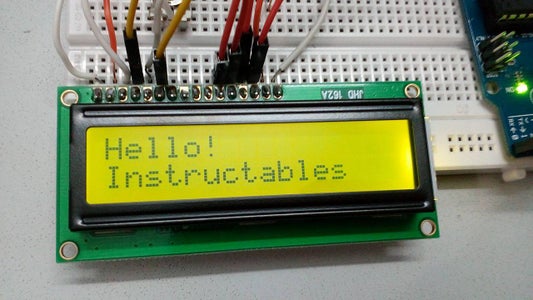
The LCD should display -
Hello!
Instructables
...................................................................................................................................................................................
Enjoy LCD interfacing. You should go through the Liquid Crystal library of Arduino Liquid Crystal Library
for more functions and can create very awesome projects. Have fun!

Participated in the
Make it Glow Contest 2016


