

Introduction: ARDUINO IR REMOTE (USE YOUR OLD REMOTE TO CONTROLL HOME APPLIANCES)


In this project you can choose any remote or a TV remote which you are using and you will notice that some keys are useless for your tv for that you can use that keys for controlling the home appliences like powering your TV,FAN,LIGHTS etc...
you need to follow the simple procedure from the video so that you can record hexa values for that particular key and put into the program of the arduino
Step 1: WATCH THE VIDEO
Step 2: THINGS NEEDED


The things needed for the following project are
1.ARDUINO UNO OR CLONE
2.IR RECIVER
3.ANY OLD REMOTE
4.RELAY MODULE
5.JUMPER WIRES
6.ARDUINO IDE
7.SOME LED'S
IF YOU WANT TO MAKE A RELAY MODULE BY YOURSELF YOU COULD NEED (OPTIONAL)
1.RELAY
2.BC547 TRANSISTOR
3. 1K OHM RESISTOR
4.COPPER DOT PCB
Step 3: RECIVING THE IR CODE FROM REMOTE BUTTON
This is the test to recieve the hexadecimal code of the remote button
1.install the ir remote library form the following link in the arduino / library folder
https://github.com/z3t0/Arduino-IRremote
if you already have the library installed follow the next step
2.open the arduino ide and open example/IRrecvDemo sketch into the arduino ide
3.upload the code to the arduino.
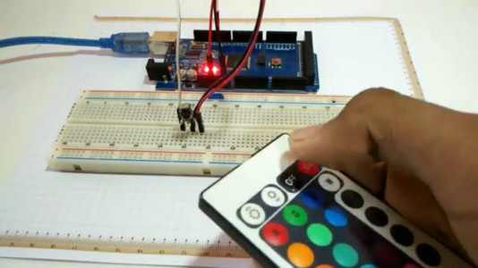
4.now connect the ir reciver to the arduino as shown in the video.
5.open the serial monitor in the arduino ide.
6.press any button on the remote and note the hexadecimal value of the button pressed
7.now you have the code of the button you can follow the next step
Step 4: MODIFYING THE ARDUINO CODE

YOU COULD USE THE FOLLOWING SKETCH TO MAKE 1 APPLICATION CONTROL
#include<IRremote.h>
int RECV_PIN = 11;
int state;
int led=13;
IRrecv irrecv(RECV_PIN);
decode_results results;
void setup()
{
Serial.begin(9600);
pinMode(led,OUTPUT);
state=0;
irrecv.enableIRIn(); // Start the receiver
}
void loop()
{
if (irrecv.decode(&results))
{
if(results.value==(0xpaste your hexadecimal code for example "0xF730F4" )
{
if(state==0);
{
digitalWrite(led,HIGH);
state=1;
}
else
{
digitalWrite(led,LOW);
state=0;
}
Serial.println(results.value, HEX);
irrecv.resume(); // Receive the next value
}
delay(100);
}
AFTER UPLOADING THE FOLLOWING SKETCH TO THE ARDUINO CONNECT THE LED TO THE PIN 13 OF ARDUINO AND IR RECIVER OUTPUT TO 11 PIN OF ARDUINO TEST IT USING THE SAME REMOTE BUTTON WHOSE HEXADECIMAL CODE YOU HAVE COPIED.
IF YOU WANT TO INCREASE THE NUMBER OF CONTROLS
THEN YOU CAN USE THE MORE NUMBER OF DIFFERENT INT FUCTIONS FOR EXAMPLE
int light=13;
int fan=12;
int tablefan=11;
int tubelight=10;
and similarly the pinmode in the void setup as
pinMode(light,OUTPUT);
etc..
similarly in the void loop section include the hexadecimal code of the button and repeat the loop as many time your number of controls
Step 5: ADDING RELAY MODULE


YOU COULD BUY A 5V RELAY MODULE FROM ONLINE AND CONNECT IN THE FOLLOWING WAY
ARDUINO RELAY MODULE
+5V------------------------->+5V
GND------------------------>GND
13--------------------------->IN1
12--------------------------->IN2
11--------------------------->IN3
10--------------------------->IN4
AND THE SAME PROCESS REPEATS FOR THE NUMBER OF CONTROLS YOU HAVE
CONNECT THE NEUTRAL WIRE OF THE MAINS POWER SUPPLY(AC) TO THE NORMALLY OPEN SIDE OF THE RELAY AND THE LINE WIRE TO HOME APPLIANCE(BULB) THE THE SECOND WIRE FROM THE BULB WILL GO TO THE CENTER PIN OF THE RELAY
[ WARNING:: PLEASE DO NOT TRY TO PLAY WITH THE 240V AC POWER SUPPLY THAT CAN KILL YOU IMMEDIATELY ]
BEFORE CONNECTING THE RELAY MODULE DIRECTLY TO AC SOURCE CHECK THE CONNECTIONS TWICE AND MAKE SURE EVERYTHING IS CORRECT
Step 6: MAKING THE RELAY MODULE(OPTIONAL)

IF YOU WANT TO MAKE A RELAY MODULE BY YOURSELF THE YOU CAN FOLLOW THE GIVEN SCHEMATIC AND CREATE YOUR MODULE
Step 7: THANKS FOR WATCHING
THANKS FOR WATCHING THE FOLLOWING INSTRUCTABLES IF YOU DO LIKE THE PROJECT AND HAVE ANY QUESTION PLEASE LEAVE THE COMMENT BELOW
DON'T FORGET TO VIEW MY OTHER VIDEOS ON THE YOUTUBE CHANNEL
https://www.youtube.com/channel/UCZE35bOktFxu8dIad...
MY OTHER INSTRUCTABLE LINKS ARE
ARDUINO WIRELESS LED DISPLAY BANNER(24X6 LED DISPLAY)
https://www.instructables.com/id/ARDUINO-WIRELESS-L...
[ WARNING : DO NOT PLAY WITH AC SUPPLY WITHOUT ENOUGH KNOWLEDGE BE SURE AND SECURE BEFORE USING THE AC SUPPLY ]

Participated in the
Arduino Contest 2016

Participated in the
Green Electronics Contest 2016


