

Introduction: The Most Annoying Alarm Clock Ever!


This project is dedicated to all those lazy students who have sacrificed their important (though not so important) classes to get the comfort of 'that one extra hour' of morning sleep. (Especially the person who is currently writing this with eyes half closed)
"The war between your attendance and sleep is never-ending and painful." - Me :')
*yawns*
This crazy alarm clock will surely wake you up, even when you're in deep sleep! It has an ultra-loud bike horn which might be useful/disappointing for your neighbor too (depends). That's why I don't suggest this thing if you're living in an apartment or if you have rude neighbors (use it at your own risk). However, you can replace the horn with a super bright LED panel which will probably be enough to open up your eyes + not disturb others.
If that super loud horn still isn't enough to wake you up and disable the alarm within 30 seconds, a servo motor with a connected cup of water will be triggered and will hence throw water on you. To still be asleep, you must be dead or from another planet.
I got this idea when I was fed up of waking up late every morning . The alarm clock on my phone failed, even after having 5 different alarms set with an interval of 5 minutes. (I stay up late at night almost daily)
____________
The clock is powered by DS1307 based real time clock module, which has the ability to store/process the time and date. It is powered independently by a small 3v coin cell and can run for over an year, thus allowing the clock to display real time even after it has been restarted. Rest of the work is done by the arduino nano used here, which displays the time on a 16x2 LCD. With the help of 3 buttons, desired alarm time can be set which gets feeded into internal EEPROM of arduino. This means that the alarm time won't change even if you switch off and restart the clock.
Disabling the alarm is not as simple as just pressing a button (otherwise it would have failed the main purpose of this project). Two LEDs are connected over two buttons, so the user will have to press the button corresponding to the LED which glows. This has to be repeated 5 times. If the user does't wake up within 30 seconds of the alarm getting triggered, arduino will direct the servo to rotate and throw water (as mentioned above). The horn will still keep on ringing (after 30 seconds), with the LCD displaying a message to restart the clock now (failing to disable).
__________
Here's a video tutorial of the build process:
Subscribe to my YouTube channel for more such awesome DIYs!
Share the project with your super lazy friends who seriously need this! :D
Don't forget to vote for this instructable in the contests entered and hit the Follow button.
Any questions/feedbacks are always welcome. Drop a comment below or leave me a mail: agrawalsanyam946@gmail.com
(Parts for this project were provided by GearBest.com)
Step 1: Parts and Tools


Here is a list of parts and tools required to build this project:
Parts:
- Arduino Nano/UNO (https://www.gearbest.com/boards-shields/pp_278172.html?lkid=11408145)
- 16x2 Liquid crystal display (https://www.gearbest.com/other-accessories/pp_216639.html?lkid=11408229)
- DS1307 based RTC I2C real time clock module (https://www.gearbest.com/development-boards/pp_45160.html?lkid=11408249)
- Ultra-loud electronic horn for bike (https://www.gearbest.com/bike-bells-and-locks/pp_374411.html?lkid=11408267)
- Standard servo motor
- Relay module for arduino
- 6v 5Ah Lead acid rechargeable battery (or any other power source)
- 1x 7805 Voltage regulator
- 3x Momentary push buttons- large
- 3x 10K resistors
- 2x LEDs- red and green
- 2x 330 ohm resistors
- 1x Screw terminal
- Female-Female and Male-Male jumper wires
- Male/Female headers
- Battery connectors
- Perforated board
- Plywood
- Spray paint
- Wire
- A small disposable cup
Tools:
- Soldering iron w/ wire
- Hot glue gun w/ glue sticks
- Multi purpose rotatory tool w/ drill bits
- Wire cutter/stripper
- Pliers
- Hacksaw
- Screwdriver
- Super glue
Total cost of parts: $37 approx. (2360 INR)
You can find almost all the parts mentioned above at reasonable rates from GearBest.
Also, have a look at their ongoing sales:
The Fall 3D Printer and Electronic Tools Promotional Sale
Creality3D CR - 10 3D Printer (coupon: CR10ZUI) $369.99
Step 2: Prepare the Bike Horn


I got this ultra-loud bike horn from Gearbest which easily served the purpose of this project. It is powered using a 9V battery and is loud enough to grab your neighbor's attention.
The battery is included inside the housing but is not initially connected. So open up the horn and remove the plastic covering from the battery. Attach the battery clip with correct polarity and put it back inside. Check if it works by pressing the button. Place the cap with screws.
This one was for bicycles so it had a little momentary push button. We don't need the button so a relay will be used as a switching device.
Cut off the switch wire with most of the wire left from the horn side. Now peel off the two wires. Joining them will complete the circuit to switch on the horn.
Step 3: Design a Shield for Arduino


To make connections easier, I always prefer jumper wires over soldering. This also makes it super simple to swap connections or to add/remove parts and make modifications.
For arduino nano, I soldered some female headers on a piece of perfboard such that the male pins on arduino can be inserted easily. Now corresponding to each female header, I soldered male headers with some extra ones for 5V, Gnd, A4 (SDA) and A5 (SCL) pins which are used more. With all the connections removed, this thing can also be used easily for other projects in the future.
Step 4: Solder the 5V Power Supply Circuit


There's an in-built 5V voltage regulator on the arduino nano. But sometimes it may not be sufficient. Extracting too much power from it will reset the arduino everytime. Here we have a servo motor, a relay and an LCD, so I soldered a simple 5V power supply circuit with L7805 regulator.
The power input pins are soldered to a screw terminal where the battery will be connected. For 5v and Gnd outputs I soldered 4 female headers for each because these two pins are required for each component we connect.
(Have a look at the complete project schematic above)
Step 5: Solder the Buttons and LEDs on Perf Board


Three buttons are used here to set the alarm time and to disable the clock. First one is used to take the clock to alarm time setting mode while the other two are used to increase hours/minutes and to switch from hours to minutes respectively.
Button 2 and 3 are soldered just below two LEDs so you will have to press the button correspoding to the glowing LED to disable the clock.
Solder the parts on perf board as done in the pictures above. 10K pull up resistors need to be added for each button and 330 ohm current limiting resistors for each LED.
(Have a look at the complete project schematic above)
Now 7 wires need to be extracted from the circuit, as you may see. Out of these 2 are for 5V and Gnd, 3 inputs for each of the 3 buttons and the rest two outputs for 2 LEDs.
Since we are using jumper wires for connections, add a male-male jumper wire to each of the extracted wires which will be later connected to arduino
Secure all the connections with tape/hot glue.
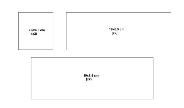
Step 6: Mark/Cut/Drill Wood to Make a Box


We're going to make a rectangular wooden box to place all the electronics inside.
Cut 2 pieces measuring 19 x 7.5cm each.
2 pieces measuring 19 x 6.5cm each.
2 pieces measuring 7.5 x 6.5cm each.
Sand and clean up the sharp edges.
Now for the front panel, you need to place the LCD and the button circuit we soldered in the last step. So measure and mark the placement of both the parts and cut off the required amount of wood such that they fit properly. Also, drill two holes for mounting the LCD using screws.
On the right panel, drill one small hole for the horn wire to pass through. On the left one, drill one small hole and one bigger for the wires from servo motor and battery.
Step 7: Paint and Stick the Wooden Panels


Using Spray/Acrylic/Enamel paints, color all the wooden panels (I used black).
Using a bottle of super glue or got glue gun, stick the front, right, left and lower panels together.
The rest of them will be added after all the connections are done.
Step 8: Connect the Power Supply and RTC Module


Using male to male jumper wires, start by connecting the RTC module and power supply circuit to arduino.
RTC:
- Vcc ---- 5v on arduino
- Gnd ---- Gnd
- SDA ---- A4 (analog pin 4)
- SCL ---- A5 (analog pin 5)
Power supply:
- 5v Out ---- 5v on arduino
- Gnd ---- Gnd
(Have a look at the complete project schematic above)
Attachments

Step 9: Connect Rest of the Parts


Start connecting whatever's left now.
The most important one here is the LCD. A 16x2 liquid crystal display has 16 pins, out of which 8 pins have to be connected to arduino. (This is not I2C type, which requires only 4 pins)
Apart from this, you also need to connect a potentiometer to adjust the contrast of the display. Pins 1, 5, 16 are always connected to ground and pins 2, 15 (which is for backlight) are connected to +5v. Connecting each of them using separate jumper wires can make things untidy. So what I did was, after soldering male headers to the 16 pins on a new/unused LCD, I soldered and connected all the Gnd pins together using some thin wire. Pin 15 is the backlight pin, which was connected to Pin 2 via a 100ohm current limiting resistor (which is recommended). At last, I connected a 10K Preset (a small potentiometer) with the left pin of preset going to Pin 1 on LCD, right pin going to Pin 2 and middle one going to Pin 3 (to avoid confusion, you can download the project schematic attached below). The preset was then hot glued at the back of the LCD. The loose wires and resistors were also covered with hot glue to make everything permanent (as you can see above). The LCD now can easily be used and connected in any project with only 8 jumper wires.
This is how you have to connect it:
- Pin 1 ---- Gnd on arduino
- Pin 2 ---- 5v
- Pin 4 ---- D2
- Pin 6 ---- D3
- Pin 11 ---- D4
- Pin 12 ---- D5
- Pin 13 ---- D6
- Pin 14 ---- D7
Next comes the circuit consisting of buttons and LEDs.
- Vcc ---- 5v on arduino
- Gnd ---- Gnd
- LED 1 ---- D10
- LED 2 ---- D11
- Button 1 ---- A0
- Button 2 ---- A1
- Button 3 ---- A2
At last, connect the relay module. I had the one with grove connectors so I used male-female wires with the male part going to grove female connector cable.
- Vcc ---- 5v on arduino
- Gnd ---- Gnd
- Signal ---- D12
(Have a look at the complete project schematic below)
Attachments
Step 10: Place Everything in the Box


Mount the liquid crystal display first, on the front panel using 2 screws. The button + LED circuit has to be hot glued from the back such that it sticks firmly.
Now add two wires to the screw terminals on the relay which will be later connected to the bike horn. The wires should pass through the drilled hole on right panel.
Similarly, add two wires to the power supply circuit which are to connected to the battery.
At last, add three male-female jumper wires with the female side connected to pins 5v, Gnd and D9 (digital 9) on arduino. These three wires will be connected later to servo motor.
Carefully hot glue all the modules and circuits inside the box. Make sure the wires do not tangle.
Step 11: Connect the Bike Horn and Attach Battery Connecters


The two switch wires from the bike horn have to be soldered to the connected wires from relay. Add heat shrink tubing after joining them properly.
For the 6V lead acid battery, I soldered two battery connectors to the power cables.
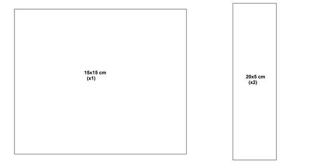
Step 12: Make a Stand for Water Spilling Mechanism


This part will be kept separate from the main box with all the electronics. The mechanism consists of a wooden base with two rectangular panels connected together, with the other one tilted such that water from the glass falls directly on the person lying below.
Cut a square base measuring 15 x 15cm and two more rectangular panels measuring 20 x 5cm each.
You can paint all the wooden parts. I covered them using white paper.
Place the first one on the base using a metal clamp and screws. The second one has to be fixed over the first at an angle of 45 degrees. Now place the servo at the top. A big hole has to be made on the servo attachment. Finally attach a plastic cup of water to the servo shaft with a small wooden/metal piece (refer the images above).
The glass should be facing downwards when the servo is at 180 degrees position.
Step 13: Install Libraries/ Set Time/ Upload the Code to Arduino

For a new real time clock module, you need to feed in the current time and date first (skip if time and date has already been fed before). For this, download the libraries named "DS1307RTC" and "Time" from below. Go to your arduino IDE and select 'include library' under sketch. Click on 'add .ZIP library' and select the downloaded zip files separately. The libraries will now be imported.
Restart IDE open the example code named 'SetTime' under file>examples>DS1307RTC. Upload it to your arduino board. Now go to the serial monitor (with the arduino connected to your PC). The time will automatically be uploaded to the RTC chip and will be displayed on the serial monitor.
For the main code, a different RTC library is used so you'll need to download that as well. Download the zip file named 'RTClib' and import it to your IDE following the same process as mentioned above. Restart IDE.
Now download the main project code and it should upload without any errors. Make sure the board, processor and COM ports are set correctly under Tools.
The basic code was taken from a project named Arduino Based Digital Clock with Alarm by CircuitDigest and then some additions and modifications were done.
#include <wire.h> // import libaries
#include <EEPROM.h>
#include <RTClib.h> #include <LiquidCrystal.h> #include <Servo.h>
Servo myservo; RTC_DS1307 RTC;
LiquidCrystal lcd(2,3,4,5,6,7);
int temp,inc,hours1,minut,add=11; // declare variables int next=A0; int incr=A1; int set_alarm=A2; int led1=11; int led2=12; int count=0; #define buzzer 10 int HOUR,MINUT,SECOND; void setup() { Wire.begin(); RTC.begin();
myservo.attach(9); // attach servo to pin 9 myservo.write(0); // position at 0 degress lcd.begin(16,2); // declare lcd as 16x2 pinMode(incr, INPUT); // the 3 buttons as input pinMode(next, INPUT); pinMode(set_alarm, INPUT); pinMode(buzzer, OUTPUT); // relay and 2 LEDs as output pinMode(led1, OUTPUT); pinMode(led2, OUTPUT); digitalWrite(next, LOW); // set all at low initially digitalWrite(set_alarm, LOW); digitalWrite(incr, LOW); digitalWrite(led1, LOW); digitalWrite(led2, LOW); digitalWrite(buzzer, LOW); lcd.clear(); // clear screen lcd.print(" Annoying "); // print lcd.setCursor(0,1); lcd.print(" Alarm Clock"); delay(2000); if(!RTC.isrunning()) { RTC.adjust(DateTime(__DATE__,__TIME__)); } } void loop() { count=0; int temp=0,val=1,temp4; DateTime now = RTC.now(); // take out values from RTC chip if(digitalRead(set_alarm) == 1) // set Alarm time { lcd.clear(); lcd.print(" Set Alarm "); delay(2000); defualt(); // function time(); // function delay(1000); lcd.clear(); lcd.setCursor(0,0); lcd.print(" Alarm time "); lcd.setCursor(0,1); lcd.print(" has been set "); delay(2000); } lcd.clear(); lcd.setCursor(0,0); lcd.print("Time:"); lcd.setCursor(6,0); lcd.print(HOUR=now.hour(),DEC); // print hours lcd.print(":"); lcd.print(MINUT=now.minute(),DEC); // print minutes lcd.print(":"); lcd.print(SECOND=now.second(),DEC); lcd.setCursor(0,1); lcd.print("Date: "); lcd.print(now.day(),DEC); lcd.print("/"); lcd.print(now.month(),DEC); lcd.print("/"); lcd.print(now.year(),DEC); match(); // function check if current time is equal to alarm time delay(200); }
void defualt() // fuction to print time { lcd.setCursor(0,1); lcd.print(HOUR); lcd.print(":"); lcd.print(MINUT); lcd.print(":"); lcd.print(SECOND); }
void time() // fuction to set alarm time and feed into internal EEPROM { int temp=1,minuts=0,hours=0,seconds=0; while(temp==1) { if(digitalRead(incr)==1) { HOUR++; if(HOUR==24) { HOUR=0; } while(digitalRead(incr)==1); } lcd.clear(); lcd.setCursor(0,0); lcd.print("Set Alarm Time "); lcd.setCursor(0,1); lcd.print(HOUR); lcd.print(":"); lcd.print(MINUT); lcd.print(":"); lcd.print(SECOND); delay(100); if(digitalRead(next)==1) { hours1=HOUR; EEPROM.write(add++,hours1); temp=2; while(digitalRead(next)==1); } } while(temp==2) { if(digitalRead(incr)==1) { MINUT++; if(MINUT==60) {MINUT=0;} while(digitalRead(incr)==1); } lcd.setCursor(0,1); lcd.print(HOUR); lcd.print(":"); lcd.print(MINUT); lcd.print(":"); lcd.print(SECOND); delay(100); if(digitalRead(incr)==1) { minut=MINUT; EEPROM.write(add++, minut); temp=0; while(digitalRead(next)==1); } } delay(1000); }
void match() // function to check if current time equals alarm time { int tem[17]; for(int i=11;i<17;i++) { tem[i]=EEPROM.read(i); } if(HOUR == tem[11] && MINUT == tem[12]) {
digitalWrite(buzzer, HIGH); lcd.clear(); lcd.print("Wake Up Pal!");
digitalWrite(led1, HIGH); int var=1; int a; for(a=30; a>=0; a--) // loop to run for 30 seconds { lcd.clear(); lcd.print("Wake up Pal!"); lcd.setCursor(0,1); lcd.print(a); if(count==5) // check if all buttons are pressed { a=-2; break; // if yes then come out of loop } if(var==1) { if(digitalRead(incr)==HIGH) // if button to corresponding led is pressed { count++; var=2; digitalWrite(led1, LOW); digitalWrite(led2, HIGH); // switch off led and switch on the other one } } if(var==2) { if(digitalRead(next)==HIGH) { count++; var=1; digitalWrite(led2, LOW); digitalWrite(led1, HIGH); // switch off led and switch on the other one } } delay(1000); } if(a==-2) // if all buttons are pressed in current order { digitalWrite(buzzer, LOW); // switch off buzzer lcd.clear(); lcd.print("Alarm Disabled"); delay(60000); // wait for 1 minute digitalWrite(led1, LOW); digitalWrite(led2, LOW); } if(a==-1) // if time goes out { while(true) // run an infinite loop { lcd.clear(); lcd.print("Wake Up Now!!"); lcd.setCursor(0,1); lcd.print("Restart Clock!"); myservo.write(100); delay(5000); } } } }

Step 14: Put on the Back Cover


After everything is in place, put on the upper cover first using super glue.
The back cover has to be removable to make any modifications in the future. I added two small folded metal clamps and placed them on the two side panels. Two holes were then drilled on to the back cover and it was placed in position with two screws.
Step 15: Finish


Join the 3 wires that were left unconnected to the servo.
- Vcc (red) ---- 5v
- Gnd (black) ---- Gnd
- Signal (yellow) ---- D9 (which is a PWM pin)
Now just connect the battery and it should display the current time. If it doesn't, re-check all connections and try again. Go back to Step 13 if the time is not set correctly.
To set alarm time:
- First press button 1
- To increase hours press button 2
- To move to minutes press button 3
- To increase minutes again press button 2
- At last, to set press button 3 again
You can use any kind of power supply between 6-12V. For continuous use, adapter is recommended instead of battery. However, it can still run for several days on a 5Ah battery. 18650 batteries can also be used.
__________
That's it from my side. I hope there'll be some good use for this project :')
Don't forget to vote for this instructable in the contests entered. Hit the follow button and subscribe to my YouTube channel for more such awesome projects.
Share this idea with your lazy friends who really need it! :D
Thanks for reading! :)

Participated in the
Audio Contest 2017

Participated in the
Plastics Contest


