

Introduction: Wifi Dot Matrix Sign


What is a wifi RGB LED matrix sign and why?
A wifi matrix sign is a low resolution screen with a web-server that anyone can access from anywhere in the world and send messages to. That's right YOU can send me a message straight to my living room without having to even get up, know my email address or phone number... what a time to be alive :)
For the why. I wanted one, it was too expensive to buy and I knew I could build one better than most non wifi signs.
The good things about having a led sign
Other peoples opinions, insults, thoughts, happenings and desire to express themselves in form of emojis are no longer restricted to social media. Now I can get all that straight to my living room and can get blasted by it on a daily basis from the comfort of my couch… yaay :D
For the non sarcastic good thing about having a sign
It is quite useful for display of daily information like date, time, outside temperature and bus schedule etc and all that is great and all... But the best part is that it is a blast at parties where people just spam the sign with weird messages to each other.
Enough with the chit chat lets get started.
Step 1: Planning
Before diving into material gathering it is a good idea to do some planning and calculations. This sign can be made as big as you want and the resolution is also entirely up to how you build and what material you use.
I decided after a lot of thinking to go with a 30 column 8 rows leds array which required at least 240 leds. The leds are bought in meters where you usually can choose how many leds/meters you want. I decided to go with the 60 leds per meter roll which meant that I needed 4 meters for my 240 led setup.
A couple of things to consider when deciding the size of the matrix is that if you build it the way I did there won’t be any multiplexing of the leds which means that power consumption will be of greater importance, especially since these leds are driven by 5V and not 12 like other strips. In short power consumption, will be proportional to the amounts of leds in your sign.
The LEDs
The leds that are used are ADDRESSABLE 5050 RGB LEDs. I wrote that in caps since there are a lot of different led strips out there on the market and they work differently so for this project only the addressable or programmable leds will work. These leds are usually more expensive than the ordinary RGB 5050 leds but look the same. The difference is that with the addressable leds you can program individual colors on individual leds as contrary to the ordinary RGB strip where you're only able to light up the whole strip and where all leds are in the same color. Other differences are that the addressable leds are all connected in parallel and because of that they require 5V instead of the usual 12V for a strip and also they don’t have RGB input but rather data in/out (DI/O) and sometimes a clock (clk) signal and because of that they require a microcontroller to be utilized.
Step 2: Power Consumption


Multiplexing is when only a portion of the screen is lit up a fraction of the time before going to the next portion. By doing this in a fast enough manner the screen will appear to be all lit up due to persistence of vision (google for more info). The advantage of doing this is that power consumption will only be as high as the size of the maximum lit portion but with the price that the screen will seem more dim. (just google multiplexing matrix for more information about this)
Since I decide not to multiplex the light, which on one hand means that I can turn on all the leds at once and turn this sign into a VERY bright light panel, means on the other hand that power consumption will be an issue with increasing amount of leds.
Each led is said to draw 60 milliamps (mA) on full brightness according to the eBay site I got them from. This means that if I turn the sign on to full brightness on all leds the sign will draw 0.06 * 240 = 14,4A, which is a lot! During normal use the sign won’t even be close to these kinds of power consumption but since Murphy and his law is a well-known enemy of mine I decided to calculate with worst case scenario.
Handling 14+A is not fun at all and would require way too big cables, not to mention heat problems. So to solve this power issue I realized that I’d have to portion down the power to the leds and go with many smaller drivers rather than one beefy sucker.
The total power consumption was calculated to be around 72W which there are a lot of adapters that can handle especially for laptops but then they usually run on a higher voltage than 5V. By using several mini dc-dc buck converters I could drive the whole thing from a higher voltage rather than current. Each converter could handle up to 3A and have an input range from 4,75-23V. This means that I can drive up to 50 leds. I used a total of 8 drivers for this sign where I paired them to a group of 3-4 columns of led-strips each.
This way I can feed the sign a higher voltage with less current which is easier to do than delivering 5V and 14,4A current.
Step 3: Bill of Materials and Resources
- 4m Addressable RGB 5050 led strip (I bought 5m 300leds, non waterproof)
- 8 pcs 3A DC-DC mini buck converter
- 1 length of Wires and tabbing :)
- Piece of at 16mm thick MDF for the frame (this is probably as thin as you will want to go to be able to fit all the components inside. any thinner and youll have a hard time fitting everything in)
- 2pcs of Masonite for back cover and led back plate (Back panel should be same size as frame and led panel should be 10mm smaller in hight than inner size of frame to make room for wires.)
- 1pc of acrylic clear glass (plexi) for front plate (same size as frame)
- screws
- 1pcs of piezo buzzer/speaker
- 1 NPN transistor (2N2222) and some resistors (100ohm, 1k ohm and 11k ohm)
- 1pc of ESP-01 wifi module (there are other models with built in usb connectivity [Node MCU] and such which might be a lot easier to use and handle)
- 1pc DC jack power connector
- 1pc of power switch
- 1pc of switch button
Main tools used where
- Solder iron
- X-Carve CNC machine
- Glue gun
- Multimeter
Software libraries required
- Adafruit_GFX.h
- Adafruit_NeoMatrix.h
- Adafruit_NeoPixel.h
- ESP8266WiFi.h
- espneotext.h
Files
original version
https://www.dropbox.com/sh/xzpq95mzcth4nko/AACF_bA...
with color picker: (some modification may be required)
https://github.com/dkomando/esp_neomatrix_web_text
Adafruit libraries
https://github.com/adafruit/Adafruit_NeoPixel
https://github.com/adafruit/Adafruit-GFX-Library
https://github.com/adafruit/Adafruit_NeoMatrix
Resources
Step 4: Finally, We Can Start Doing Stuff!


Since I have access to an X-Carve at my local makerspace I decided to cad the frame using fusion 360. My aim when designing this was to make it as small and portable as possible and in the end, it almost came out too small. The inner size of the frame is just large enough to fit the leds and the wires if you use a bit of force. In some places, I even had to chip away a bit of the panel to make it fit.
This project of course can be done without the help of a fancy computery machiny thingy. All you need is some kind of enclosure for it and you are good to go.
Step 5: Led Strip


When I got the leds I started cutting them in strips of 8 leds each and made sure my frame size calculations were correct. Since I only bought 4m instead of the 5m they usually come in I needed all the leds for this sign, including the end parts that were wrapped in shrink tube. I cut both ends of and soldered them together to create a strip of 8 leds. (can be seen in the video)
When it comes to the layout of the led strips there are some different ways these can be done. Since data is shifted into the leds they all need to be connected in series. There is an illustration showing the two main ways of connecting the ledsstrips. I chose the second way (all strips facing the same way) since I wanted my matrix to resemble Adafruits 8x8 matrix and thus be able to use their library. I later realized that the library was compatible with both ways of connections so you can basically connect anyway you want as long as you stick with it through the whole matrix.
At first I ddin’t realize there was this extensive library for led matrices for Arduino so I actually planned on making my own library. However after some research I realized that there were quite a few options available out there and so the connection of the strips are not really that important as long as you stay consistent.
Step 6: Solder and Testing


During the build I used an Arduino nano and adafruits neopixel strandtest to test the leds and make sure they all worked properly.
Once you’ve got the led panel and it’s painted to the color you wish, it its time to start sticking the led strips to it and prepare for a lot of soldering. During soldering be gentle while bending the wires from the led strips under the panel. One thing I realized was that the copper padding you solder on are really fragile and rips off for basically no reason at all. If that happens you won't be able to retach the wire so if this happens on the DI or DO connection you might render that strip useless for the matrix. However if it happens on a power or ground wire you can do some cross connections between led strips to fix it. The best way to avoid these kind of accident is to use thin and flexible wires and not to put too much tension on the pad.
All the DC-DC converters are connected in parallel from the power input and are used to drive 3 or 4 columns of led-strips each. This is to not risk driving them on their max rated current since the rated 3A is peak current rating. It is important to remember to adjust the output voltage of the converters to 5V before soldering them on to the led strips or you might fry your leds since a lot of these converters are set to a higher voltage from start.
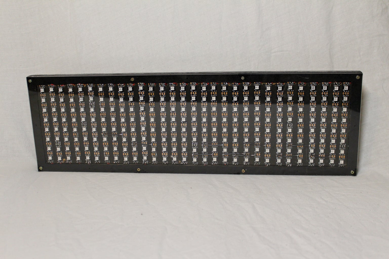
One thing that might be confusing looking at the picture of the wire connections is that there are a lot of red wires, both long and short. The long wires going all the way from the top of the panel to the bottom are data wires and not power wires. They are connected from DO to DI of the strip. At the time I didn’t have any other color so I had to go with red. The 5V red wires are a bit thicker and are connected to tabs. So all the positive 5V poles are connected from one side of the strip and all ground is connected on the other side, connecting to a ground rail.
Step 7: Sound


Once the actual panel is done we can move on the internal electronics.
I wanted some kind of audible notification from my sign to notify me whenever someone sent a message to it. For this a piezo buzzer would prove perfect, so I took one that I had lying around that I’d scavenged from some old toy or something. These little buggers usually require a higher voltage than the ESP can deliver to make enough sound to be satisfying. So I added a transistor and connected it to 5V from a one of the converters. This gives enough sound if you are in a quiet to normal environment. However I noticed the sound was not enough during parties when loud music is being played.
Step 8: ESP Wifi Module


I used an ESP-01 for this project.
This was my first project using an ESP module so I didnt quite know which one to buy that's why I went with the 01 model. In retrospect this was a bit limiting and a bit of a hassle to get started with since you needed a serial programmer to flash it, which I luckily had. Also the pins arent breadboard compatible, which adds to the hassle.
Another drawback with the 01 is that you only have two pins to work with and for this project that was enough but It might be quite restricting if you plan to add more features to your sign.
I'm not gonna go into detail on how these ESPs work but one thing to know if you’re not familiar with the ESP is that to flash it you need to put the GPIO0 pin to ground at boot. This became an issue later when I thought I was done and tried to start my sign. The reason for it didnt boot proparly was that I had connected the led data to the GPIO0 pin which apparently pulled it down to low thus throwing the ESP into flash mode at every bootup. So to solve this I added a switch in between that disconnects the leds. So to start my sign I first have to disconnect the led data connection by pressing the pushbutton, then power on the sign through the main power switch and lastly reconnect the led data to GPIO0.
If you decide not to add sound to your sign or you have more pins available on your ESP then it is adviced to avoid using GPIO0 and instead use other pins to avoid having to do this ritual at every startup.
Another thing that I realized was that I had to replace the pins that were on the ESP to be able to fit it under the led panel. So I de-soldered all the pins and attached wires directly to the ESP and then extended them to pins.
Step 9: Software
My plan was to write my own library for this project. But after a bit of research I realized that there already were a few matrix libraries out there for Arduino ready to be used so... I got lazy.
The libraries I used for this project were Adafruits neopixel, neomatrix and GFX library and also a ESP8266 library to get web interface. As I said before I’m not going to go through all the differences and details of the software so you’ll have to do that research yourself depending on what you want. All the files needed to get started can be found in step 3 (Bill of materials) and also you'll find useful links to help you on the way.
I will however mention that there are some things that needs to be configured for the bare minimum matrix to work. For bare minimum I recomend using Samir Sogays code as it is the Matrix in it's simplest form. You will need to set some parameters according to how the strips are connected, how many pixels are in horizontal vs vertical and where the first led is etc but thats all well commented in the files. For a complete understanding of the different configurations I recommend you read the header file for each library where all the functions are described.
If you wish to customize the web interface this can be done too but this of course require some understanding of how web design works.
For the sound I wrote a small function that is quite self explaining.
Step 10: Assembly and Final Testing


For the power switch, DC jack and disconnect switch I used a drill to drill large enough holes on the side to be able to fit the components.
Once you've managed to flash the ESP and connected everything just assemble it and give it a go to see it works.
I've had mine running for a couple of days and people still love it and cant stop spamming it when they visit. I will however improve mine quite a lot and add extra features in the coming future.
Step 11: Possibilities
After using this matrix sign for a while I’ve come to realize a lot of possibilities with it. I could for instance feed current temperature, time, date straight to the sign and also get updates on the local bus schedule. I could also connect it to twitter to get twitter feeds straight to the sign or why not stock prices or headlines from a news source? I haven’t done any of this yet but I plan to do some it in the near future to make this sign as useful as possible.
It would be nice to have a karaoke mode on this sign...
For now it’s just used by my friends to send random messages and to display propaganda in the house so there sure is some space for improvements.
That’s about it folks hope you enjoyed this instructable and let me know if you’ve got any comments or ideas of how else I could improve this LED sign.
This project will definitely participate in some contests so hopefully you enjoyed it enough to vote for it *thumbs up*
References and special thanks to Samir Sogay
and to David Komando
https://github.com/dkomando/esp_neomatrix_web_text
Whos code I based mine on.
to send a message try going to http://82bar.sytes.net to see if the sign is on.
If the message is sent with #instructables I'll post pic of the message here in the comments in case I manage to capture it on camera :D
*disclaimer* The sign might be turned off at times due to updates or me getting sick of people spamming it.

Second Prize in the
IoT Builders Contest

Participated in the
CNC Contest 2016

Participated in the
Epilog Contest 8


