Op-Amp Challenge: A Logic-Free BCD

Of digital electronics, a wise man once said that “Every idiot can count to one.” Truer words have rarely been spoken, because at the end of the day, every digital circuit is really just an analog circuit with the interesting bits abstracted away. And to celebrate that way of looking at things, we’re pleased to present this BCD to seven-segment converter that uses no logic chips.

With cheap and easily available chips that perform this exact job, it might seem a little loopy to throw 20 LM324 op-amps at the job. But as [gschmidt958] explains, this is strictly for the challenge, plus it made a nice entry in the recently concluded Op-Amp Challenge contest. His work began in simulation, exploring op-amp versions of the basic logic gates — NAND, AND, OR, and NOT — all of which rely on using the LM324s as comparators. There were real-world curveballs, of course, not least of which was running out of the 10k resistors used for input averaging. Another plot twist was running out of time to order a PCB, which required designing one using MS Paint and etching it at home.

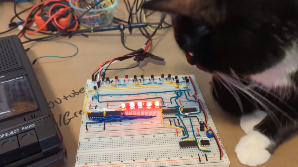
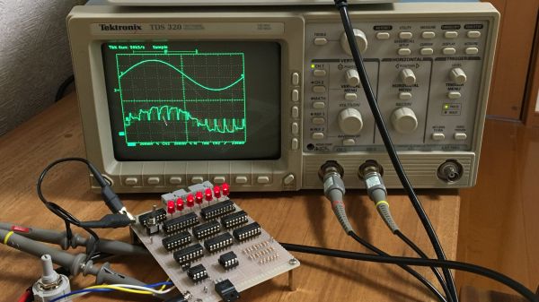
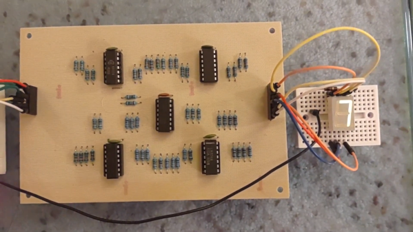
The demo video below shows the circuit at work, taking the BCD output of a 74HC393 counter — clocked by a 555, naturally — and driving a seven-segment LED.  It’s honestly a lot of work for such a simple task, but there’s something satisfying about the whole project. We think [Widlar] would be proud.

Continue reading “Op-Amp Challenge: A Logic-Free BCD”

Tiny PCB Banishes Soldering Fumes, Automatically

A fan to remove fumes is a handy thing to have when soldering, even better is a fan furnished with a filter. Better still is a fan that activates only when the iron is in use, turning off when the iron is in its stand. Now that’s handy!

[Petteri Aimonen] made exactly such a device when he noticed his JBC BT-2BWA soldering station could detect when the iron is removed from its stand, and indicate its operating mode via status LEDs. Broadly speaking, when the iron is removed from its cradle the green “in use” LED is on. By turning the fan on whenever that LED is lit (and turning it off when it becomes unlit), fume extraction gets a little more elegant and efficient.

Instead of tapping directly into the soldering station’s hardware to detect the LED’s state, [Petteri] went for a completely noninvasive solution that made good use of a few spare parts and a small bit of copper-clad board. The PCB is nothing more than piece of copper-clad board with lands scratched out with a hobby knife.

This tiny board sits atop the soldering station, parking a photodiode directly above the “in use” LED. The circuit is a simple comparator whose output controls fan power via a MOSFET, and a top-facing LED provides as a duplicate “in use” indicator, since the original is hidden under the tiny board.

Even for one-off designs like this, creating a PCB layout in an EDA program like KiCad is still worth doing because one can use it to scratch out lands on a copper-clad board, a technique with similarities to Manhattan-style circuit construction.

A Cassette Interface For A 6502 Breadboard Computer, Kansas City-Style

It’s been a long time since computer hobbyists stored their programs and data on cassette tapes. But because floppy drives were expensive peripherals and hard drives were still a long way from being the commodity they are today, cassettes enjoyed a long run at the top of the bulk data storage heap.

Celebrating that success by exploring the technology of cassette data storage is the idea behind [Greg Strike]’s Kansas City decoder project, which he hopes to use with his [Ben Eater]-style 6502 computer. The video below explains the Kansas City standard in some detail, and includes some interesting historical context we really hadn’t delved into before. There are also some good technical details on the modulation scheme KCS used, which [Greg] used to base his build. After a failed attempt to use an LM567 tone decoder chip, he stumbled upon [matseng]’s KCSViewer project, which decodes KCS-encoded audio signals using nothing but discrete components.

[Greg]’s prototype has a comparator to convert sine waves to square waves, followed by pair of monostable timers, each tuned to either the high or low frequency defined in the KCS specs. A test signal created using Audacity — is there anything it can’t do? — was successfully decoded, providing proof of concept for the project’s first phase. We’re looking forward to the rest of the series, which will turn this into an actual decoder, and presumably add an encoder as well.

Listeners of the Hackaday Podcast may recall we experimented with using KCS to hide some data within an episode a few months back.

Continue reading “A Cassette Interface For A 6502 Breadboard Computer, Kansas City-Style”

The No-MCU Fan Controller

The default for any control project here in 2019 was to reach for a microcontroller. Such are their low cost and ubiquity that they can be used to replicate what might once have needed some extra circuitry, with the minimum of parts. But here we are at the end of 2021, and of course microcontrollers are hard to come by in a semiconductor shortage. [Hesam Moshiri] has a project that takes us back to a simpler time, a temperature controlled fan the way they used to be made, without a microcontroller in sight.

Old hands will no doubt guess where this design is heading, there is an LM35 temperature sensor producing a voltage proportional to its temperature, and half of an LM358 which forms a comparator against a static voltage from a divider. The LM358’s output drives a MOSFET which in turn switches on or off the fan motor. This type of circuit used to be the daily fare of simple control electronics in the days when a microcontroller represented a significant expense, and it’s still a handy circuit to be reminded of.

Have you forgotten sensors such as the LM35 in a world of on-board sensors? Time to refresh your sensing memory.

Successive approximation register ADC

Homebrew Circuit Explores The Mysteries Of Analog-to-Digital Conversion

When it comes to getting signals from an analog world into our computers, most of us don’t give much thought to how the hardware that does the job works. But as it turns out, there are a number of ways to skin the analog to digital conversion cat, and building your own homebrew successive approximation register ADC is a great way to dispel some of the mystery.

From his description of the project, it’s clear that [Mitsuru Yamada] wasn’t looking to build a practical ADC, but was more interested in what he could learn by rolling his own. A successive approximation register ADC works by quickly cycling through all possible voltage levels in its input range, eventually zeroing in on the voltage of the input signal at that moment and outputting its digital representation. The video below shows how the SAR ADC works visually, using an oscilloscope to show both the input voltage and the output of the internal R-2R DAC. The ADC has an input range of 0 V to 5 V and seven bits of resolution and uses nothing but commonly available 74xx series logic chips and a couple of easily sourced analogs for the sample-hold and comparator section. And as usual with one of his projects, the build quality and workmanship are impeccable.

We love these sorts of projects, which are undertaken simply for the joy of building something and learning how it works. For more of [Yamada-san]’s projects, check out his 6502-based RPN calculator, or the serial terminal that should have been.

Continue reading “Homebrew Circuit Explores The Mysteries Of Analog-to-Digital Conversion”

[Ken Shirriff] Picks Apart Mystery Chip From Twitter Photo

It’s no secret that the work of [Ken Shirriff] graces the front pages of Hackaday quite frequently. He’s back again, this time reverse engineering a comparator chip from a photo on Twitter. The mysterious chip was decapped, photographed under a microscope, and subsequently posted on the internet with an open call to figure out what it did.

[Ken] stepped up, and at first glance, it was obvious that most of the chip is unused, and there appeared to be four copies of the same circuit. After identifying resistors and the different transistor types, [Ken] found differential pairs.

Differential pairs form the heart of most op-amps, and by chaining them together, you can get a strong enough signal to treat it as a logic signal. Based on the design and materials, [Ken] estimates the chip is from the 1970s. Given that it appears to be ECL (Emitter-Coupled Logic), it could just be four comparators. But there are still a few things that don’t add up as two comparators have additional inverted outputs. Searching the part number offered few if any clues, so this will remain somewhat a mystery.

We’ve covered [Ken’s] incredible chip sleuthing before here, such as the Sharp EL-8 from 1969.

Should Have Used A Vacuum Tube 555

“You should have used a 555” has become a bit of a meme around these parts lately, and for good reason. There seems to be little that these ubiquitous chips can’t be used for, and in a world where code often substitutes for hardware, it’s easy to point to instances where one could have just used a simple timer chip instead.

Definitely not in the meme category, though, is this overkill vacuum tube 555 timer. It comes to us via [David Lovett], aka [Usagi Electric], who has lately caught the “hollow state” electronics bug and has been experimenting with all sorts of vacuum tube recreations of circuits we’re far more used to seeing rendered in silicon than glass. The urge to replicate the venerable 555 in nothing but vacuum tubes is understandable, as it uses little more than a pair of comparators and a flip-flop, circuits [David] has already built vacuum tube versions of. The only part left was the discharge transistor; a pentode was enlisted to stand in for that vital function, making the circuit complete.

To physically implement the design, [David] built a large PCB to hold the 18 vacuum tubes and the handful of resistors and capacitors needed. Mounted on eight outsized leads made from sheet steel, the circuit pays homage to the original 8-pin DIP form of the 555. The video below shows the design and build process as well as testing of all the common modes of operation for the timer chip.

You can check out more of our coverage of [David]’s vacuum tube adventures, which started with his reverse-engineering of an old IBM logic module. And while he did a great job explaining the inner workings of the 555, you might want to take a deeper dive into how the venerable chip came to be.

Continue reading “Should Have Used A Vacuum Tube 555”