

Introduction: Smartphone Controlled Arduino Robot


Last time I showed how to hack an RC toy and make it into Arduino Bluetooth control car, This time is how you how to make a Smartphone Controlled Arduino Robot, if you are new to Robotics , you might consider using Arduino as its easy to learn flexible with huge examples to follow and with huge no. of chassis available it is easy for anyone to make a Robot.
Previous one was complex as i was using Arduino pro mini and hacking the internal circuit this one far easier and less frustrating .
link : https://www.instructables.com/id/Arduino-Bluetooth-...
This is up for the circuits contest if you like it do vote
You can watch the video.If you like subscribe Update weekly .
Step 1: Parts and Tool Required

I brought this Robot kit which contains everything you need to get started with robotics and the price was low also
only 70 $
Robotics Kit : http://amzn.to/2dxbeH7 70 $
Individual Items
- Arduino Uno http://amzn.to/2fo01ij 10$
- Arduino Sensor Shield http://amzn.to/2dVVCC5 7$
- Jumper cables Female to Female http://amzn.to/2fo0DEL 4$
- 2x 18650 battery http://amzn.to/2eUQmLB 10 $
- 2x 18650 battery holder http://amzn.to/2e6jUEy 5$
- 18650 battery Charger http://amzn.to/2efOm2d 10$
- Robot chassis http://amzn.to/2dVWS8j 22$
- Bluetooth module http://amzn.to/2e6mDxC 8$
- Motor Driver Module http://amzn.to/2foa8U7 9$
Which is 15$ more the kit prize but compared to the other accessories for other bot build it is way cheaper.
Step 2: Mounting the Motors


The motors that come with the kit are BO motors which are usually what you start with robotics .
The Bo motors are mounted on the chassis using an Aluminum rectangular block , this block is provided with any kit or chassis you buy.The Block are attached with M3 Torx screw and nuts . Then using the block the motors are attached to the chassis with screws.Care must be taken that the screws are tightly attached else it will go out on drive or wobble.
Step 3: The Motor Driver


Now when the motor are attached we would need to control them . Arduino can't directly give them commands , it will need a motor driver circuit i.e H-bridge
What is a Motor Driver ?
An H bridge is an electronic circuit that enables a voltage to be applied across a load in either direction. These circuits are often used in robotics and other applications to allow DC motors to run forwards or backwards.
About the L298D
he LN298 is a high voltage, high current, dual full-bridge motor driver designed to accept standard TTL logic levels and drive inductive loads such as relays, solenoids, DC and stepping motors.
Step 4: Connecting the Motors
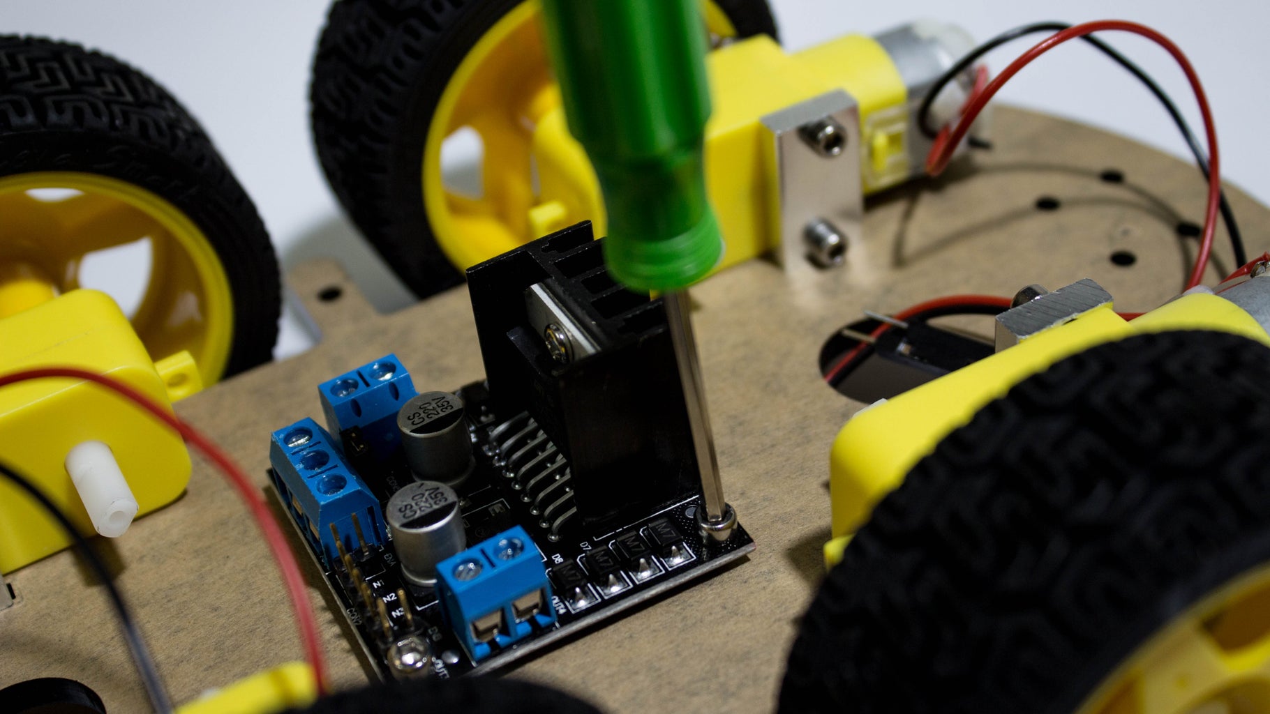


Mount the L298 Module
Using the Screw and nut attach the module first to the chassis .
Connections
L298D GND to battery box
L298D Positive to Battery box positive
Left Motor pair Positive to Mn1
Left Motor pair negative to Mn2
Right Motor Pair positive to Mn3
Right Motor Pair positive to Mn4
Connect 6 jumpers from ENA ,IN1,IN2,IN3,IN4,ENB
this will be connected to the Arduino to control the motors
Step 5: Attach the Metal Spacer and Wheels


After finishing connecting the motors with the L298D , screw the six spacers to the chassis to connect the bottom layer with the upper layer . Use the screw to fix it in place .
Attach the wheel also in the mean time,Fix the wheels tightly or it will wobble out and trust me this happened to be once :P
Step 6: Power Source


Well, the most important thing more a robot is the energy it has to do something ,this energy is supplied from batteries. Now for driving four motors u will need a lot of energy ,with high drain capability so we choose Lithium ions batteries. These kit came with 2 18650 battery along with a great charger . These 18650 battery are 2600 mah .
and has enough juice for the robot to have some fun you can use also two mobile battery connected in series as a source.
Step 7: Attaching the Arduino and Battery Box


The next step is to get the brain on the board mount the Arduino Board and the battery box on the top layer. The process is similar .
Connections
Battery Box positive to Dc jack Postive ,
Battery Box negative to DC jack GND
Connect the DC jack to the Arduino's Female Jack
Step 8: Final Work


Attach the lower layer with the top layer with the spacer and screws. Mount the Arduino Sensor shield on the Arduino UNO and make the final connections.
Connections
ENA to Arduino pin 10
IN1 to Arduino pin 9
IN2 to Arduino pin 8
IN3 to Arduino pin 7
IN4 to Arduino pin 6
ENB to Arduino pin 5
Connect the Hc-05/Hc-06 to serial pins on the Sensor shield
Else connect
Arduino 5V to hc-05 vcc
Arduino GND to hc-05 Gnd
Arduino TX to hc-05 Rx
Arduino Rx to Hc -05 Tx
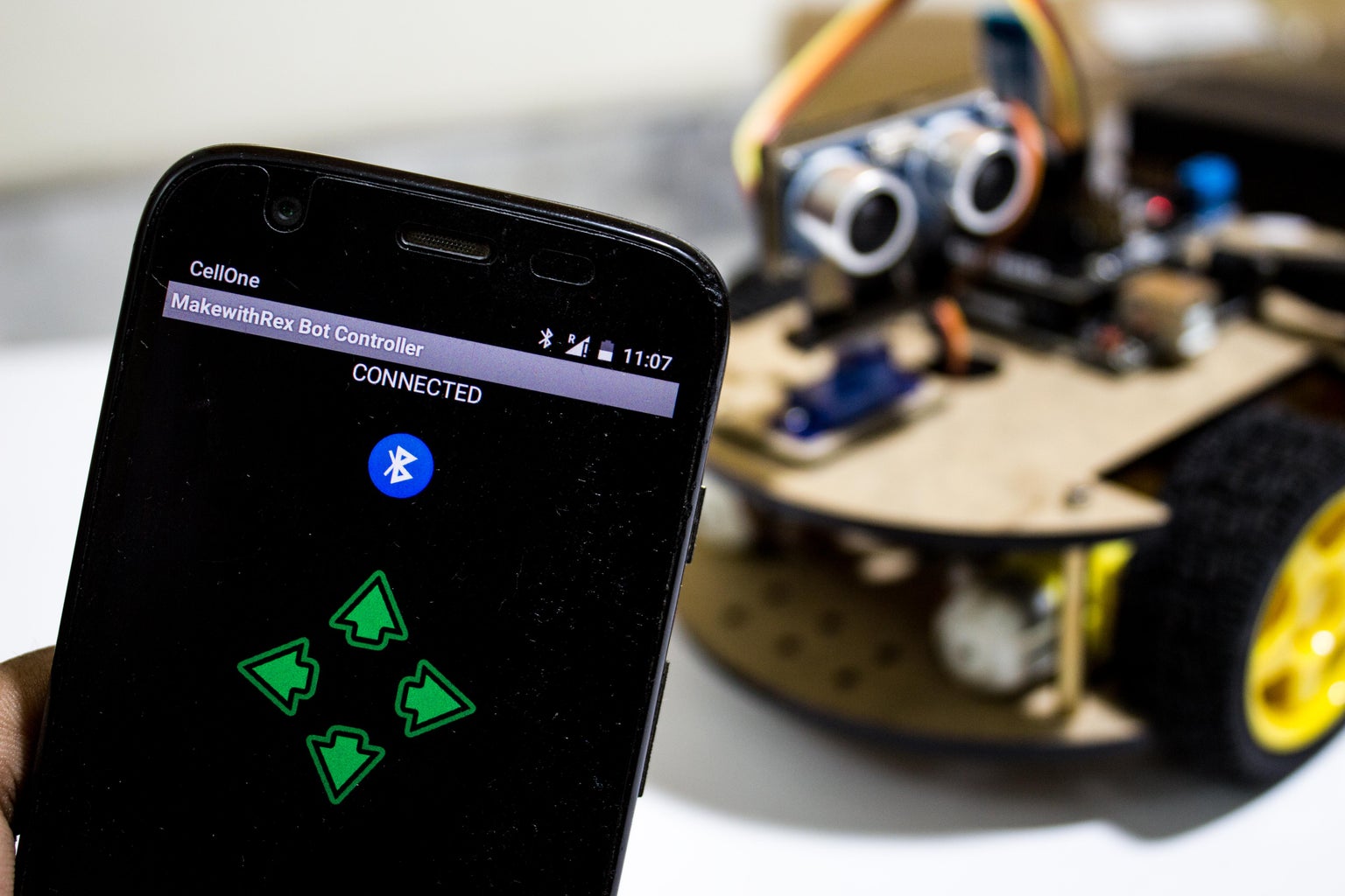
Step 9: Software (app and Code )


Download the app https://goo.gl/RlW912
This app is the newer version of the Arduino bot controller that I built last time if you want I can make a tutorial on how to make an app like this.
The app connects to the Arduino via hc-05 and sends data via Bluetooth which then the Arduino compares with given condition.
Attachments

Step 10: Future Plans

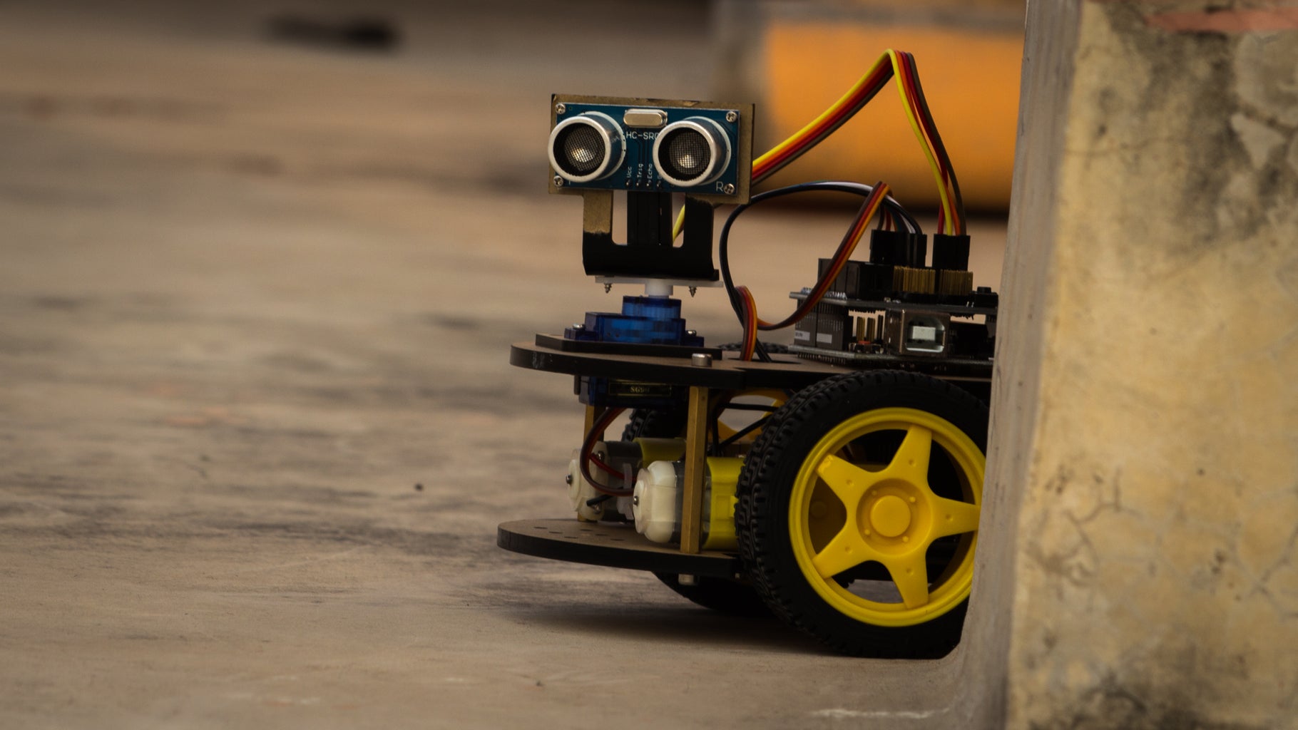
The next plan would we to try to make the obstacle detector, as you can see the sensor is already on :P so it will be sometime soon that I will update it also I would like to try make a line follower, you something who knows :O
like my page to get notified of every single activity I do and tell what you love to see.
https://www.facebook.com/makewithRex/
Also Subscribe to my channel i update weekly

Participated in the
Circuits Contest 2016


