

Introduction: Pretty Useless Machine


A catapult "gets rid of" the red thing. A robot "brings the red thing back to the catapult." Cooperatively, these devices busily work together at conflicting goals to accomplish nothing (insert your analogy here).
Step 1: Parts
This requires 3d printing, electronic work and wood work. Print all of the 3d parts (two of the wheels). Wheels and the "thing" should be printed at 100% fill. The "thing" must be a bright color (one the Pixy camera can find), but a color that (in the camera's view) only exists on "the thing."
(4) Arduino Unos
(2) Nextrox Mini 12V DC 60 RPM High Torque Gear Box Electric Motors
(2) TOOGOO(R) 37mm DC Geared Motor Mounting Bracket Holder
(2) Eureka vacuum belts (tires for the wheels)
(1) Servo gripper unit--from Jameco.com
(2) Servo motors (I use Hitec)
(1) High Torque servo motor (to pull the catapult spring)
(1) Servo motor with the mechanical stops and electronics removed (gear motor to operate actuator)
(1) Ping ultrasonic transducer
(1) Pixy camera
(8) NiMH AA batteries
(1) Battery holder for 8 AA
(1) SPDT switch
(2) Arduino Motor Shield
(4) Infrared Sensor
Plywood, 1 x 4, wood screws, electrical tape, jumper wires, solder
Note: The 3d files for the actuator (GM Leadscrew, etc.) were modified from a design by Chiprobot (http://www.thingiverse.com/thing:317192)
Attachments
 arduino holder design.123dx
- arduino holder.stl
- base combo.stl
- battery holder design.123dx
- battery holder.stl
- camera tilt bkt.stl
- caster base.stl
- catapult arm.stl
- extend plate.stl
- witch wobble base.stl
- wheel-1.stl
- stop posta design.123dx
- servo hornd.stl
- servo 0908 lid.stl
- rodlong.stl
- rings.stl
- nickel plug.stl
- line follow bkta.stl
- line follow bkta design.123dx
- ir start holder.stl
- GM_LeadScrew_003.stl
- catapult stopper.stl
- caster ball.stl
- camera bracketa.stl
- body bracketd.stl
- body.stl
- camera bracketa design.123dx
- plungerbkta.stl
- spacer.stl
- stop posta.stl
- stop sw bktd.stl


Step 2: The Thing

Print the parts (witch wobble base should be scaled to 85% of original size). Acquire four nickels (or similar size coins for weight).
Step 3:


Insert the coins in the base and the plastic plug above the coins.
Step 4:

Insert the rod in the "rings" and glue or melt together.
Step 5:

Glue or melt the rod assembly to the base. This "thing" will always land rod side up.
Step 6: Lifter (linear Actuator)

Cut off the ends of a servo horn and attach the horn to a servo gear motor (normal servo motor with internal end stops and electronics removed).
Step 7:

Attach the 3d printed servo horn.
Step 8:

Push this into the leadscrew and secure with a 2-56 screw and nut.
Step 9:

Place the servo bracket against this assembly, making sure that the motor shaft can turn freely. Melt the servo bracket to the assembly using a soldering iron (or glue them together).
Step 10:

Attach the gripper unit to the extend plate.
Step 11:

Attach a servo motor to the gripper.
Step 12:

Attach the gripper assembly to the actuator assembly.
Step 13:

Glue the servo lid to the servo motor bracket.
Step 14:

Add the ping holder to the bottom of the servo bracket, then fasten the ping detector to the bracket.
Step 15:

Attach the motor brackets and motors to the body. Use the vacuum belts on the wheels as tires, then push the wheels onto the motor shaft. Attach the lifter assembly to the body (drill holes as needed).
Step 16:

Add the caster base and wheel to the rear of the body. Add the camera bracket.
Step 17:

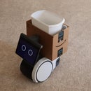
Add the camera bracket, Pixy camera and an Arduino. Install the sketch in the Arduino and attach the Pixy camera to the Arduino.
In this step, I'm adding vision capability for the robot.
Let's examine the operation of the vision system. Pixy is trained to a color--push the white button on top until the Pixy LED turns red then release. Place the target color (my red wobbler "thing") in front of the lens until the LED turns more or less the color of the target "thing". Press the white button and release--the LED should flash to indicate acceptance. The Pixy camera detects color blobs (providing location information about them) and works best in a controlled light environment. In other words, if the light source changes, Pixy will have trouble seeing the selected color--Pixy is trained to a color/light source combination. In my setup, the red led (attached to the Arduino) blinks when the object is to the right. The white led blinks when it is to the left. When straight ahead (or nothing visible), both led's are off.
Attachments
Step 18:


Add the battery holder bracket and the Arduino holder platform. Add the battery holder and the switch.
Step 19:


Add wires to the Ping transducer (I used wire wrap wire) and bring the wiring to the appropriate Arduino.
Step 20:

Most of my connections were made using jumper wires and a breadboard.
Step 21:

A "line follow" bracket was printed. To this I mounted two infrared sensors and wires--this assembly is mounted on the bottom of the robot.
Step 22:


The catapult parts are printed and assembled using bolts and nuts.
Step 23:

A spring is attached to the high torque servo motor and the catapult arm. I used 22 gauge wire wrapped a few times to secure the spring to the catapult arm.
Step 24:


The end stop and ir sensor are added to the catapult assembly.
Step 25:

An ir assembly is added to the robot.
Step 26:

Install the various sketches into the appropriate Arduino.
Step 27:

When the "thing" arrives on the catapult, the ir sensor detects it--then, after a time delay, the spring servo puts tension on the arm, The release servo is actuated and the "thing" flies through the air. The spring servo resets, then the release servo resets.
Step 28:

The robot (after a delay to allow the "thing" to land and quit wobbling) commences a search using the Pixy camera. If it sees the "thing," it will go to it to pick it up. If not, the robot will go straight until it hits a wall, then the higher current of a stalled motor will be detected and the robot will reverse, turn, and continue the search.
When the Ping ultrasonic detector indicates that the "thing" is within the gripper, the robot stops, gripper closes and actuator rises. The robot then reverses, hunts the black line and follows the line until the robot ir detector indicates arrival at the catapult. The gripper is opened, the robot backs up, turns and waits--then repeats.
A few afterthoughts: The blue painters tape is not necessary, I just place it under the electrical tape so that the electrical tape would not "stain" the wood. I may want to paint the floor and line at some point in the future.
Did I need to use so many Arduinos? Maybe not, but it is easier with my limited software capability to assign tasks to a processor and avoid keeping up with tricky timing (like measuring overload current to the motors while timing the return signal of ultrasonic sound, etc.)

Participated in the
Arduino Contest 2016

Participated in the
Design Now: 3D Design Contest 2016


