


Last year I bought a generic 350-watt unicycle and loved it, but I soon realized how limited its performance was: about 9mph (15km/h) top speed, maybe 5–6 miles (8–10km) of range, and poor climbing ability. So I thought I would upgrade it with a more powerful motor and make it a real means of transportation, with good speed and enough range to actually go somewhere without having to worry all the time about running out of juice.
Online I bought a 500-watt motor and controller from Shenzhen MicroWorks with impressive specs at a very reasonable cost. But then I realized I needed a completely new enclosure with room for more batteries. Finding nothing suitable, I decided to design my own and 3D print it myself.

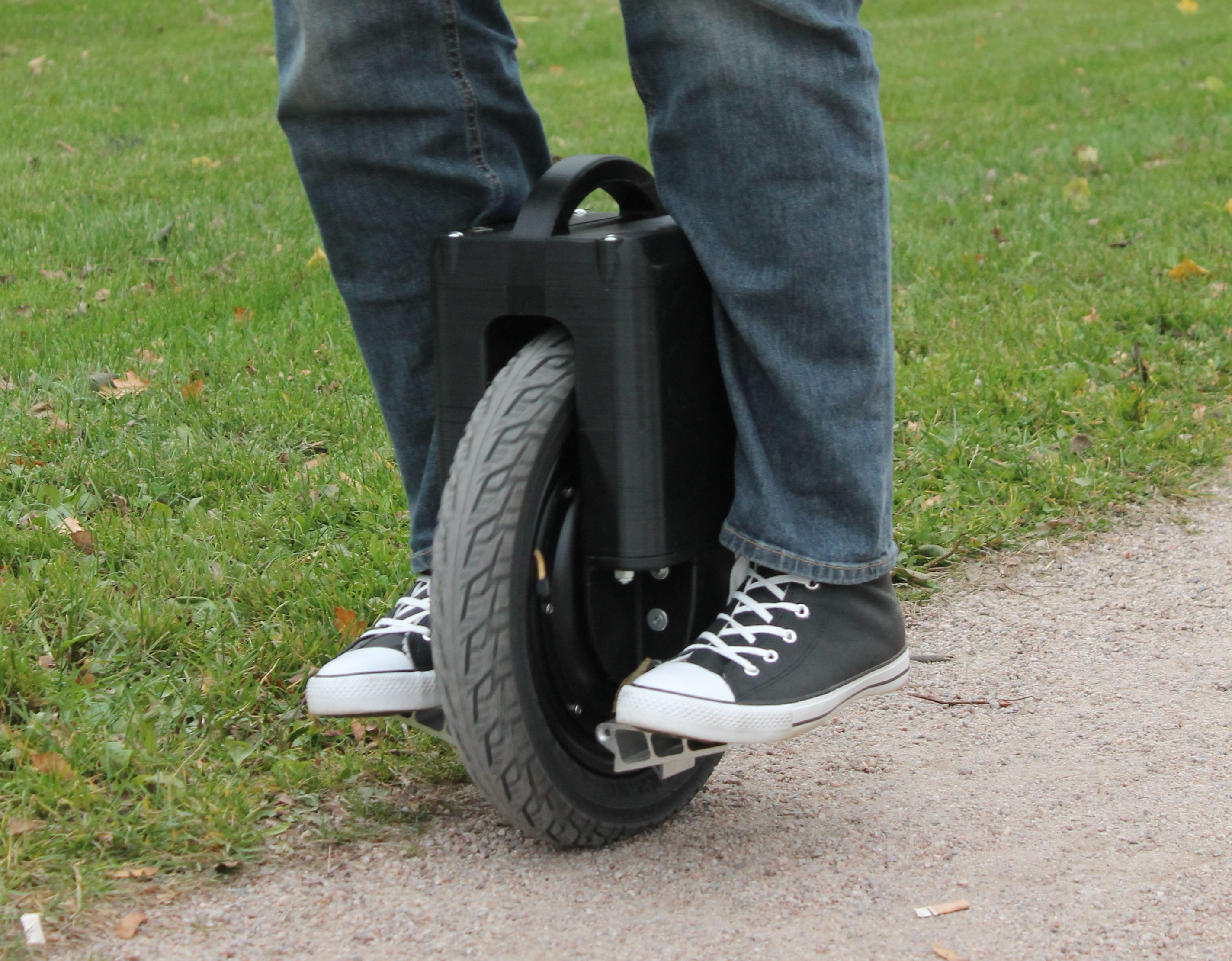
It worked great! This project is my updated version: the E14S Electric Unicycle. It’s more compact, with better ergonomics, but with the same impressive range and performance as its predecessor. Where my old version used four 16-cell battery packs (16S1P) connected in parallel, this new version uses 2 packs of 32 cells (16S2P), so the battery housings can be smaller with the same total capacity. Also, this version uses a horizontal speed controller board, so the housings on both sides are available for batteries, for excellent weight distribution.
The essential structure is the same: The housing is printed in sections that are then stacked and secured with M8 threaded rods that go through the whole structure from top to bottom. These housings are bolted to each other crosswise through the top handle section, also using M8 rods. The new horizontal mainboard goes in the space underneath the top handle.
I’ve tried to keep the design as simple, compact, and smooth as possible. I recommend using PLA filament to avoid warping issues. Be aware that these parts are large and will take a long time to print.
With the motor I used, the unicycle’s top speed is around 20mph (30km/h), and at full battery capacity your range should be around 25 miles (40km) in actual road conditions. You’d have to spend $1,100 or more for a top-of-the-line unicycle to get similar performance. It is really a joy to ride.
CAUTION: This is a high-powered unicycle not recommended for first-time riders. We recommend you develop your riding skills on a less-powerful machine before upgrading to a 500W motor like this one — it will save you a lot of banging up your 3D printed parts, and your shins!
YOU PRINT IT, YOU RIDE IT!
Before you step aboard, you must calibrate the horizontal position of your unicycle according to your board manufacturer’s instructions. The MicroWorks board has a Bluetooth app for that — but it’s in Chinese and not easy to use. Luckily older versions of the GotWay app are compatible with the MicroWorks motor, and there’s also a new open source app, EGG Electric Unicycle. Both of these are in English and fairly easy to set up and use. First you pair your electric unicycle controller (EUC) board with an Android phone or tablet, via Bluetooth. Then you calibrate your EUC’s upright position and you’re ready to ride. It only takes a couple of minutes (Figure L).

There are 3 riding modes to choose from. Soft mode is the softest and “Madden” mode the firmest. I recommend you start with Madden mode, or possibly Comfort mode, but Soft mode is so soft that I had trouble keeping my balance when I tested it. The app also has plenty of other useful info like current speed, battery voltage and charge, board temperature, and how many amps the motor is drawing (Figure M).

Charge your unicycle’s batteries fully (if you haven’t already).
Tie a strap about 2′-3′ long to the handle so you can hold onto it while you ride. This strap is not intended for keeping your balance while you’re riding — it’s a safety strap so you can catch the unicycle and keep it upright if you have to dismount suddenly, so that it will stop, instead of running off and crashing. The unicycle can move on its own in an unpredictable and dangerous fashion when it tips over. Keep using this strap until you learn to step on and off gracefully.
Step on and start riding. Use safety gear (helmet at a minimum, skate pads and shin guards if you’re being extra careful) — it’s fast!
CAUTION: Riding a unicycle is not the easiest skill to acquire, even on an electric unicycle. If you’ve never ridden before, we suggest you watch lots of videos on YouTube first (such as this one) and check out online guides like the Electric Rider. It takes some practice, but once you’ve got the hang of it, you’ve got an amazing personal commuter vehicle that will stow under your desk — and you built it yourself!
WEATHER RESISTANCE
People have asked me whether the unicycle can be used in rainy conditions. The answer is that it can be made quite water resistant by adding silicone in between the printed parts and covering the LED openings with tape or by filling them with transparent silicone. Also the power switch could be replaced with a splash-proof version and the charging port covered with a rubber cap. With those changes, your electric unicycle should be able to handle quite a bit of rain.
COSTS, PART SOURCING, AND BATTERIES
When my editors asked me to break down the cost of this project (in U.S. dollars), here’s how I figured it:
— Minimum: Parts from Microworks with freight: $250 + filament $40 + one 16S battery pack $70 (minimum to get it running) + hardware parts $15 = $375
— Minimum with full range: Microworks $250 + plastic $40 + hardware parts $15 + 64pcs 18650 cells from Gearbest: $176 + 2pcs 16S BMS boards from aliexpress: $39 = $520
This second option means you have to make your own battery packs, like I did, using for example 64 individual lithium cells such as the ones from Gearbest linked here, and two battery management system (BMS) circuit boards such as the ones from Aliexpress.com linked here. These lithium cells are brand cells, but a lower priced version. They are reliable, have good capacity (2600mAh) but put out less current (5.2A) than higher priced cells, which put out 20A or so. However, since there are four of them working in parallel, you´ll still have perfectly sufficient current output. But if you only use 16 cells in your setup, then you should buy more expensive cells with higher output current (20A or more).
— Easiest with full range: If you order complete 16S2P battery packs, like most people probably will, then the battery cost will be about $370–$400 for a total cost of around $700.
— Premium with full range: If you use more expensive batteries with even higher capacity cells, maybe some more expensive filament, and buy the connectors locally then you might spend as much as $800 or more.
So based on my experience, the price range is about $375–$800. You could go even much lower than $375 if you use salvaged cells from laptop batteries to build your own battery packs — but that’s probably a story for another article. And of course if you use a print service it’ll be more, but I haven’t asked for any quotes. Still, this breakdown should help you make a pretty accurate estimate of your costs, should you choose to build this project.
Good luck, and please share your build in the Comments below!