

Introduction: Automatic Cat Flap Monitor With Intrusion Detection and Dissuasion


If your cat is micro-chipped you can get a special cat flap which reads the microchip and allows only your cat to come in. But it's not cheap.
For a while we've been leaving our cat flap open and allowing Mog to come and go though the night as he pleases, as he likes to sleep in the greenhouse in the Summer. But we often wondered what he did while we were asleep. And a little while ago we had a suspicion that the new tom on the block might be coming in and stealing Mog's food.
But we weren't sure. So before spending £100 on getting Mog micro-chipped and fitting a fancy cat flap, I decided to apply a little technology to the problem.
I had pretty much all the bits I needed, so I set about building an automatic cat flap monitor.
A 3D accelerometer glued to the cat flap detects the tilt of the flap when it opens. This is continuously monitored by a Raspberry Pi, which also has a Pi camera attached. The Pi switches on a light and triggers the camera to start taking photos when it detects the cat flap opening.
All that is needed, then is each morning to review the photos taken the previous night, and to look for any evidence of the wrong cat. And as a result, the intruder has been successfully nabbed!
But can we automatically distinguish the foreign tom from Mog? No animal microchip reader seems to be easily and cheaply available. Could we automatically analyse the photos to determine the colour of the cat? Probably, but that sounds like hard work! Is there an easier way? Yes there is - read on! And how can we deter the wrong cat? I have a way, and no, it involves neither high voltages or cucumbers! (Cucumbers?? Check out cat cucumber videos on YouTube.)
Step 1: What You Need


This is what you will need:
- A Raspberry Pi, case, power supply and SDCard with Raspbian installed. Any model of Pi will do including the Zero, except for the original Zero which lacks a camera port.
- A Raspberry Pi camera and case or mount. You will probably find it helpful also to get a longer camera ribbon than the default one that comes with the camera.
- A WiFi dongle, unless you are using a Pi 3, which has on-board WiFi. Alternatively you can use a powerline network adapter as I did, because I found the WiFi less than totally reliable, probably because my router is directly behind the central heating boiler from where I needed to locate the Pi.
- A 3D accelerometer module. I used the Pimoroni one, but the MPU-6050 or MPU-9150 (which I've used on different Instructables) will work just as well. I believe the newer MPU-9255 should work but I haven't tried it. It might need an updated library.
- A 12v LED lamp. One of the G4 SMD disk ones works very well, but anything that you can mount in a suitable position will do.
- A 12V power adapter. Mine was a very old Apple charger. (Early iPods could be charged from 12V.)
- An NPN power transistor, a 4.7K resistor, a small piece of stripboard, and a short length of pin strip.
- Connecting wire or ribbon cable, jumper leads, soldering iron, solder, wire cutters.
- A hot-melt glue gun for sticking the accelerometer to the cat flap, and blu-tack to hold wires and other bits in place.
Step 2: Switching the Light


The GPIO pins on the Raspberry Pi can only switch 3.3V at a small current, so the 12V LED light must be driven by a transistor which can be controlled by a GPIO pin.
You can use almost any NPN power transistor, such as TIP31 (or TIP31A or TIP31C), BD135, BD237 or C1162 (2SC1162), but in order to use the stripboard layout unchanged, make sure the collector is the central lead. If you're not sure, an online search for the transistor type will find you a datasheet from which you can confirm which pin is which.
Cut a piece of stripboard to size and solder the transistor, resistor and pin strips to it as shown.
Using female to female jumper leads, connect the input pin to the Raspberry Pi GPIO pin 7 and the ground pin to the Raspberry Pi GPIO pin 6.
I used 2 strands cut from a spare length of ribbon cable to connect the lamp. If you use a G4 disk lamp you can unsolder the pins from the back of the disk and solder the wires in its place. Solder the other ends of the wires to the stripboard. These G4 lamps are designed to run on AC and so it doesn't matter which way round you connect it. If you use a DC lamp connect the positive and negative as shown.
Depending on what sort of 12V power supply you use the method of connection may vary. If it has a flying lead with a plug on the end you can cut off the plug and solder it to the stripboard. Alternatively, if it has a 2.1mm or 2.5mm power plug you can obtain a matching socket and connect this to the stripboard via a short flying lead. In either case it's very important to connect positive to positive and negative to negative.
You can hold the stripboard in place with blu-tac, somewhere between the Raspberry Pi and the lamp. Blu-tac is also a good way to hold the wires neatly in place.
The pair of pins in the centre of the board are for testing. If you short them together (with or without the Raspberry Pi connected) the lamp should light.
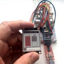
Step 3: Attaching the Accelerometer

If you use the Pimoroni accelerometer you may wish to remove the connector and solder a length of 4-way ribbon cable directly to it, long enough to reach the Raspberry Pi. (With care, you can lift off the black housing - it doesn't come off willingly - then unsolder the 26 gold plated inserts individually. If you want to you can push the inserts back into the housing in order to reuse the connector.)
The ribbon cable should connect GPIO pins 1, 3, 5 and 9 to the corresponding pins on the accelerometer.
In the case of the MPU-6050 or MPU-9150 you can solder the 4-way ribbon cable directly to it. These often come with a separate pin strip which you can use if you want to. You can use it instead on the stripboard in the previous step.
On these accelerometers the connections are labelled. Connect them as follows:
GPIO	Accelerometer
1	Vcc
3	SDA
5	SCL
9	Gnd
Where the wires are soldered to the accelerometer (whichever type you use) they will be under strain as the cat flap opens. A blob of hot-melt glue will prevent the wires from flexing and eventually breaking at the solder joint.
The accelerometer should be positioned such that the positive z axis points downwards with the flap fully open in an inward direction, and horizontal with the flap closed. (It's quite easy to modify the program if that isn't possible.)
Carefully position the accelerometer on the flap of the catflap as near as possible to the hinge, but making sure it doesn't foul the catflap frame when it opens inwards completely. There needs to be sufficient slack on the ribbon cable to allow it to open outwards completely. Now fix it to the flap with a hot melt glue gun.
If you need to remove it later you can cut through the glue with a sharp craft knife. Warming it with a hair dryer or a heat gun on a low setting will make this easier.
Secure the ribbon cable to the cat flap frame with blu-tac, leaving just enough slack to allow the flap to open fully in either direction. You can keep the ribbon cable in place at other points on the door and the wall with blu-tac.
The easiest way to connect the ribbon cable to the Raspberry Pi GPIO connector is probably to cut two female to female jumper leads in half, and solder these to the 4 strands of the ribbon cable. Insulate the joins with PVC tape.
Step 4: Setting It Up

There are plenty of tutorials coving the basic set up and operation of the Raspberry Pi. Unless you have room for a keyboard, mouse and monitor close the the cat flap you will need to set it up to run "headless", i.e. operated remotely using PuTTy or VNC over your home network.
In your home directory on the Raspberry Pi, create a directory called "catflap" and into it dowload catflap.py and either XLoBorg.py or MPU9150.py, depending on which accelerometer you are using.
If you're using the MPU-9150 you need to edit catflap.py. Change these lines near the top of the file:
from XLoBorg import *
#from MPU9150 import *
to:
#from XLoBorg import *
from MPU9150 import *
To test that everything is working, at a Terminal or PuTTy session, type:
cd catflap
python catflap.py
(Don't repeat the cd command if you've already done it in the same Terminal or PuTTy session.)
If you now open the catflap the light should come on and the camera should start taking photos. These will be stored in a daily subdirectory of catflap with a name of form yymmdd. (Small children are fascinated by this and you may find yourself with a few pictures like the one shown here!)
To make it run automatically on boot, edit the file /etc/rc.local using your favourite editor as root, or by typing the following at a Terminal or PuTTy session:
sudo nano /etc/rc.local
At the end of the file, just before the "exit 0", insert the following 2 commands:
cd /home/pi/catflap
python ./catflap.py >/home/pi/catflap/catflap.txt 2>&1 &
If you're running Raspbian Jessie it may be necessary to precede these 2 lines by one containing "sleep 10" (without the quotes) as Jessie may execute this file too early in the boot sequence.

Step 5: Detecting a Foreign Cat
I've left you in suspense so far as to how you can automatically distinguish your cat from a neighbour's. In fact it's very simple. Yours is on home ground and will generally come straight through the cat flap with little hesitation but a foreign cat knows it's on potentially hostile territory and will come through much more warily. There are two indications of a foreign cat: firstly, it may open the cat flap for several seconds just sufficiently to sniff the air for anyone inside. Then it may come only half way through and spend a while looking and listening before coming right in.
The accelerometer takes 10 measurements of the flap angle per second. In my case, more than 20 samples with the flap open by no more than around 12 degrees, or the whole event comprising more than 60 samples indicates a foreign cat. You will need to fine-tune those parameters, particularly if your cat is old or the foreign cat has become emboldened.
The catflap.py program creates 2 log files in the daily directory:
- The file catflap.txt contains a log of entries and exits. When you open or shut the door or a cat briefly nudges the briefly it will record a "transitory" event.
- The file cattrace.csv records accelerometer readings and counts during an event, allowing you to determine the appropriate threshold values for detecting an intruder.
The values recorded in cattrace.csv are:
- Accelerometer x, y and z readings (only z is used).
- Ins and Outs: counts of samples in the current event with the flap open at lease around 25 degrees inwards or outwards.
- Intruder: normally 0 but 1 if an intruder has been detected.
- Peeping: count of samples with the flap open between around 12 and 25 degrees inwards.
- More: Count of additional samples at the end of a suspicious event to keep the camera running.
Each event is preceded by a line giving the date and time. You can examine this file with a text editor or you can import it into Excel. In Excel, if you like, you can graph the z values in order to see the events better.
There are some subtleties in the code to allow the camera to take photos whilst the main code continuously monitors the accelerometer, but you don't need to understand these in order to tune it.
Find the comment "# Detect an intruder". The following line determines the intruder detection threshold: the peeping count reaching 20 (2 seconds) or the whole event so far (peeping plus ins) reaching 60. The latter is the most likely to need adjustment.
If necessary you can also adjust the peeping and flap open angles, determined by comparisons on values of z. These are currently set to 0.2 (approx 12 degrees) for peeping and 0.43 (approx 25 degrees) for fully open.
Step 6: Deterence!

Having detected a foreign cat it's a simple matter to make the Raspberry Pi play a sound file. For this you will need a USB-powered mini speaker of the type sold for connection to a smartphone. You can power it from one of the Raspberry Pi USB ports.
The video (made from the image sequence taken by the camera) shows how effective this can be. I found a sound file of a really blood-curdling angry cat yowl which I used here, but a little searching online will throw up others, or you might prefer a dog bark. Whatever you choose, make sure your own cat isn't around when you sample them!
You will also need to install the mpg321 media player. At a Terminal or PuTTy session, type:
sudo apt-get install mpg321
The catflap.py program already contains the code to invoke mpg321, ignoring the error if it isn't installed or if the media file isn't present.
Install your media file in the catflap directory and rename it as catwarning.mp3
Now you just have to wait for your neighbour's cat to trigger it. Hopefully think twice before coming in again!
.


