

Introduction: H Bridge Motor Driver for Arduino Using Transistors


Hello everyone, In this instructable we will be building our own H Bridge motor driver module for Arduino using transistors.
Technical specifications:
- Control motor speed using PWM pins of Arduino.
- Control motor direction.
- Can run any small hobby DC motor consuming 250mA (Maximum).
Why a H Bridge?
- Unlike my last attempt to control motor using a single transistor, the H bridge module consists of 4 transistors. Because, the single transistor motor driver was able to control the speed of motor. But, unable to control direction of the motor.
- So, We need a H bridge of transistors in order to control speed as well as direction of the motor efficiently.
- Also, This motor driver dose not cost any more than $1.25 USD making it super cheap.
Find the circuit on Autodesk Circuits here.
Step 1: Gather the Parts

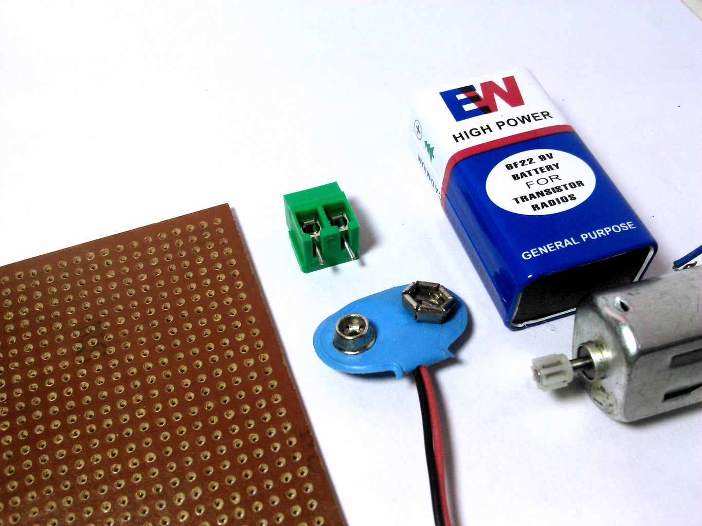
In order to build our own H Bridge Module, we will need:
- 4 x 2N2222 transistors
- 4 x 1.2k ohm 1/4W resistors
- 4 x IN4007 Diodes
- 1 x 0.1 microfarad ceramic capacitor
- 1 x Medium Perfboard
- 1 x 2-position 3.5 mm terminal block
- Male pin headers or male jumper wires.
- 9V Battery clip
- Wires
- Soldering tools
Optional parts (For power indication):
- A LED
- 1 x 220 ohm 1/4 W resistor
For running and testing the motor driver module, we will need:
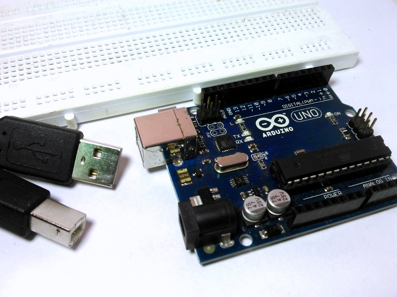
- An Arduino UNO
- A Breadboard (For prototyping)
- Small DC Motor
- 9V Battery
Step 2: Prototype

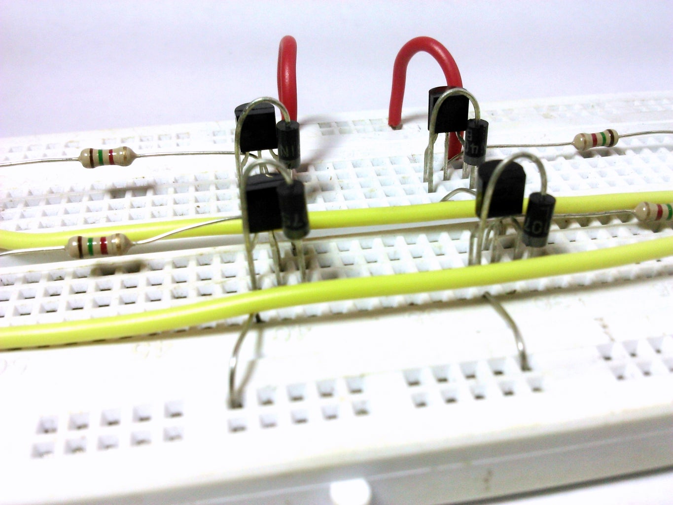

It's always a good idea to test your circuit on a breadboard before you start to solder them together.
So, hookup all the components according to the circuit diagram shown above.
Before you connect the motor:
- Solder the 0.1 microfarad ceramic capacitor to the motor to counter electrical noise.
- Yes, to counter electrical noise the best way is to connect the capacitor as close as possible to the motor.
- Ceramic capacitors are Non-Polar i.e, they can be connected either way to the motor. So, You do not need to worry about terminals of the capacitor.
Step 3: Arduino Sketch

Once you have hooked up everything properly upload the following sketch to Arduino:
What does the sketch do?
- The following sketch turns on the motor and runs it one way for 4 seconds.
- Stops the motor for a sec.
- Runs it the other way for 4 seconds.
- Stops the motor for a sec.
The above process is repeated over again and again.
void setup()
{
pinMode(9, OUTPUT);
pinMode(10, OUTPUT);
}
void loop()
{
analogWrite(9, 220); //Any value between 0 to 255
digitalWrite(10, LOW);
delay(4000);//Wait for 4 secs
digitalWrite(9, LOW);
digitalWrite(10, LOW);
delay(1000);
analogWrite(10, 220); //Any value between 0 to 255
digitalWrite(9, LOW);
delay(4000);//Wait for 4 secs
digitalWrite(9, LOW);
digitalWrite(10, LOW);
delay(1000);
}
Attachments

Step 4: Run the Motor

Power up the arduino and the motor driver. And see your motor spinning.
If you have hooked up every thing properly the motor should spin.
Troubleshooting
A) Motor not spinning:
- Make sure you have placed the transistors correctly. i.e. Flat side of the transistors is in the correct side according to breadboard layout.
- Try Re-Uploading the sketch
B) Transistors getting too hot :
- The motor that I am using does not draws more than 250mA. But, If you are using any other DC motor then it could Draw more than 1000mA easily. Resulting in heating of the transistors.
- So, make sure that you are using the right motor.
If you are still having trouble, write in the comments below.
Step 5: Prepare Perfboard for Soldering

Arrange all the components on the perfboard to get an idea about where all the parts will go.
Also, This will help to choose the right size of perfboard for soldering.
I have used a larger perfboard than, what is required to make things simple.
If you have just started with soldering checkout Instructables for awesome soldering tutorials.
Step 6: Solder the Transistors


Solder the transistors to the perfboard.
I have bended base of the transistor in order to give proper space to collector, base and emitter for soldering.
This helps in soldering the transistor properly.
Make sure that the Flat surface of NPN transistor goes the correct way. As seen in the schematics and images.
Step 7: Solder the Resistors

Solder the resistors to base of each transistors.
The resistors do not have polarity. So, they can be soldered either way.
Step 8: Solder the Diodes


Solder the diodes adjacent to the transistors.
Make sure that the stripe on the diode is pointing the correct way.
Step 9: Solder the Wires


Solder wires and 2-position terminal block to connect the transistors and other components.
I have used solid cored wires as jumpers on the perfboard.
Step 10: Solder the Pin Headers.

Solder pin headers and Battery clip to motor driver module by referring to the pictures.
I have used male jumper wires after striping one of it's end.
Why to use male pin headers?
- As a general standard if something is taking power it uses male headers and if something is giving power it uses female headers.
- So, I used male pin headers on the motor driver module.
- You can use either male headers or female headers according to your convenience.
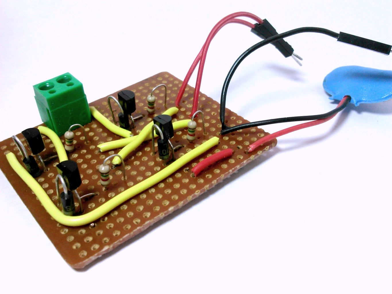
Step 11: Done

Once you have finished soldering all the components to a perfboard you are ready to go.
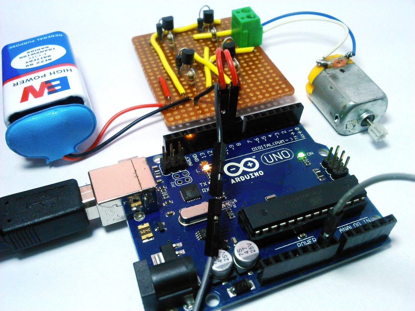
- Just attach a 9V battery and motor to the motor driver.
- Finally, connect the motor driver to Arduino and you are ready to spin your motor.
Thanks for viewing.
Further questions or suggestions are welcome.

Participated in the
Circuits Contest 2016


