

Introduction: Variable Voltage Regulator Using the LM317


hello,
today I’m gonna show you how to make an adjustable voltage regulator with the LM317.
Step 1: Watch the Video

The video is in my youtube channel Chris' Project. LInk:
Step 2: The Schematic

Step 3: Buy All of the Components
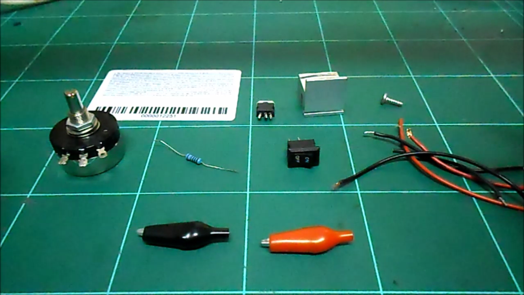
The components for this project are:
1pc old credit card.
1pc LM 317
1pc heatsink
A screw
1pc 10k ohm potentiometer
1pc 1k ohm resistor
1pc switch
Red and black wires
And a couple alligator clips
Step 4: Put the Heatsink on the Mosfet

Put the heatsink on the LM317 with the screw so the LM317 will not get hot.
Step 5: Glue the Components to the Credit Card

Glue the LM317, the switch, and the potentiometer to the old credit card.
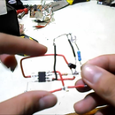
Step 6: The Connection

Solder the resistor to the adjust pin and the output pin. Then connect the adjust pin to the middle pin of the potentiometer, the output pin to the red wire, and the input pin to the other red wire.
Step 7: The Last Connection

Finally, connect the left pin of the potentiometer to the black wire, and the alligator clips to the output wires. And the switch to the red input wires. And we are done.
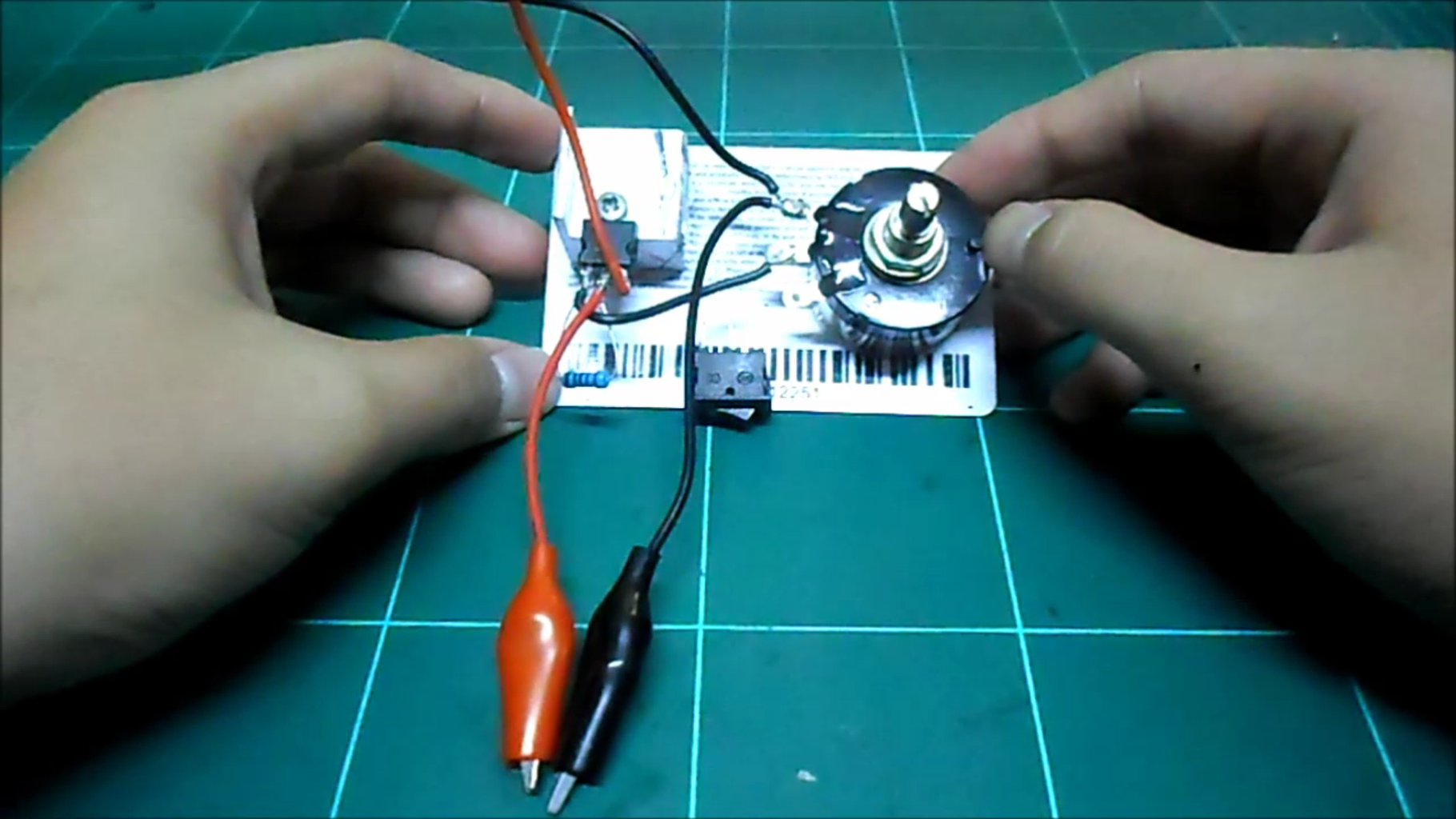
Step 8: Testing

Now I’m gonna connect the input wires to a 12V power supply and the output to my multimeter. If I turn the potentiometer the voltage will go up and go down.


