

Introduction: Follow the Line Robot


You may have seen this little line following robot on ebay they are very cheap and great for kids. This instructable is aimed at little kids or big kids who want to make a simple robot. Once you have some success with with your robot and a have had enough of it following lines everywhere, the chassis makes a great base for an arduno robot that will be able to do much more interesting things. That however will have to be an instructable for another day.
Step 1: Learning Intentions and Success Criteria
Learning Intentions
- To work safely in the workshop.
- To research electronics and understand basic electronic circuits and components.
- To operate a multimeter, soldering iron and hand tools.
- To build and fault find a line following robot.
- To be a self-directed learner.
Success Criteria
- I understand the safety rules and I am working safely in the workshop.
- I can follow the instructions independently.
- I can produce a line following robot.
- I can safely use a soldering iron to solder PCBs correctly
- I can fault find and repair a non-functioning circuit.
- I can operate a multimeter, using the correct settings and measurement units.
Step 2: Stuff You Will Need


Ebay does a follow the line robot kit for around $10. It comes instructions which wont be much use unless you can read Chinese but the PCB is well labeled, and it is a reasonably simple kit to put together. To assemble the kit you will need.
- Robot kit
- Soldering iron
- Solder
- Side cutters
- Heat shrink.
- 2X AAA batteries
- You can also use header pins and plugs on the motor leads, so you can modify your robot easily if you wish.
You will also need to be able to identify electronic components and understand if they are polarity sensitive and know how to read component values. You will also have to have good soldering skills, as many of the pins are very close together and poor soldering will ruin your project very quickly.
Step 3: How Good Are Your Soldering Skills?


If you have never done any soldering before, this is not the project to practice on. A good way to learn to solder is practicing on a piece of vero board and some header pins. Tips for good soldered joins are.
- Make sure the soldering Iron is clean, melt a little solder on the tip and clean off with a wet sponge.
- Soldering iron need to be up to temperature before you start.
- Use proper resin core 60/40 electrical solder. (Lead free solder can be difficult to work with)
- Heat the pad and the wire with the solder iron Bring the solder in from the opposite side of the iron
- Melt the solder onto the pad and wire.
- Avoid putting the solder directly on the soldering iron when soldering
- Lots of practice.
Step 4: Do You Know Your Componets?


There are a number of components you need to get familiar with before you start you have to be able identify the components and understand if they are polarity sensitive and know how to read component values. If you solder a component in the wrong place or around the wrong way your robot will likely not work.
This can easily be done with a google search, here are some names to get you started. You could draw up a grid in your folio with a row for for each of the following, or write a paragraph with dot points and a photo for each
- Resistor
- Electrolytic capacitor
- Transistor
- PCB
- IC
- IC socket
- Switch
- Trim pot
- LDR
- Electric motor
In your grid or paragraph you need 5 columns or dot points for for each of the following.
- Name of component
- photo
- symbol
- Brief description on how to read the components value.
- Is it polarity sensitive, how can you tell which way around it fits into the PCB
Step 5: Making a Start.


The resistors are a good place to start, There are four different values and they need to be in the right place. You can use a resistor colour chart to identify the values, but that method is only as good as your eyesight. My preferred method is to use a multi-meter, which is much easier to read than the colors on a resistor. The reading you get may be slightly different to the resistor value due to tolerances. You can see the multi-meter reads 45.7Ω on the 51Ω resistor this is quite normal.
- There are four 51Ω resistors and you can see in the PCB and photos where they are fitted.
- Two 10Ω
- Two 1KΩ
- Two 3.3KΩ
Once your sure all the resistors are in the right place bend the leads so they dont fall out, and solder them in.
Step 6: Adding More Componets


Next the transistors and capacitors can be fitted, they both need to be fitted around the right way.
The trim pots, switch and IC socket are next. Take care with the IC socket as the legs are often bent and will need to be straightened. Both the switch and IC socket have pins that are close together so care must be taken to ensure the solder doesn't bridge the leads.
The IC can then be fitted to the socket and this has to go in the right way around.
The 2 red LEDs can go in next and these are polarity sensitive and have to go in the right way around. The long lead is + and goes in the wide side of the triangle on the diode symbol.
Finally you can solder header pins to the pads for the motors, this will make it possible to unplug the motors without using the soldering iron.
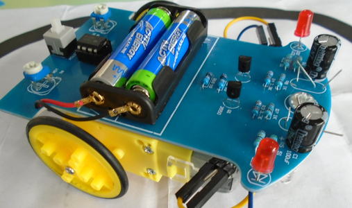
Step 7: Fitting the Motors and Battery


Wires with header plugs can then soldered to the motors and the wheels fitted with a self tapping screws. The battery pack wire are threaded through a hole in the circuit board and solder on to the pads on the PCB. The pads are very close together and the red wire goes to the +
The motors and battery pack can then be fitted with double sided tape. Make sure the motors are around the correct way and are straight. There are makings on the PCB to help locate the parts correctly.
Step 8: Fiting the LDRs and LEDs


The last four components form the line detecting sensor and have to be fitted into the PCB upside down and in the correct position. The easiest way to do this is to fit the bolt that is use as a skid an leave off the domed nut.Fit the LDRs as shown in the photos so they sit flat on the work surface and solder into position. Now refit the domed nut and the LDRs will be at the correct height.
The LEDs to be fitted a little lower than the LDRs about flush with the bottom of the domed nut.
Step 9: Trouble Shooting and What Next?

If your robot has a problem, it will most likely be either a component in the wrong place or around the wrong way or a badly solder joint. (dry joint)
You can check the resistors in the circuit with this robot, normally you need to remove one lead to read the value.
The PCB can be checked for damage with amultimeter and the photo of the copper tracks.
Once you get your robot working, You can make a big track with insulation tape, you can also experiment with your bot.
What do those trimpots do if you adjust them? What happens if the motors are wired in reverse? What happens if there is a fork in the black line? When you have had enough of it following lines, you could mod your bot with a microcontroller like an Arduino and add some sensors. Maybe even use your phone to control your bot.

Participated in the
Maker Olympics Contest 2016


