
Abstract
This work reports the fabrication of double-tubular (or tube-in-tube) carbon nanofibers (CNFs). Tetra-layered nanofibers were manufactured using coaxial electrospinning with a concentric quadruple cylindrical nozzle system. Subsequent heat treatment eroded the first and third layers and converted the second and fourth layers into the carbonized structure, resulting in double-tubular CNFs. The morphologies and microstructures of the two tubes in the CNFs were investigated, revealing that the outer layer possessed denser and higher quality carbon crystals due to the coaxial electrospinning mechanism. Nanoparticles were readily incorporated between the two tubes in the double-tubular CNFs, providing a method for developing new multi-functional one dimensional materials.
Export citation and abstract BibTeX RIS
1. Introduction
One dimensional (1D) nanostructures, such as nanowires, nanorods, nanobelts, and nanofibers, have been thoroughly investigated because of their unique material properties resulting from their unique dimensions and geometries [1]. Due to their long length, uniform diameter, and controllable compositions [2], electrospun nanofibers have been researched extensively using polymeric, ceramic, and metallic materials. For example, polymer nanofibers containing multi-walled carbon nanotubes, nanoclays, and graphenes have been reported as mechanically reinforced composites [3–5]. Ceramic nanofibers made of SnO2, TiO2, and WO3 have been researched for chemoresistive gas sensors [6–8], and ZnO and poly(vinylidene fluoride) nanofibers were used to fabricate piezoelectric nanogenerators [9–11]. On the other hand, carbon/silicon, carbon/sulfur, and carbon/tin composite nanofibers have been suggested as potential candidates for lithium-ion battery electrodes [12–14]. To enhance the performance of the aforementioned nanofiber-based applications and demonstrate new multi-functionalities, there is a strong need for an efficient fabrication method for multi-layered nanofibers [15–18].
The coaxial electrospinning process is one of the most facile manufacturing methods for multi-layered nanofibers, though many processing parameters (including surface tension, viscosity, electrical conductivity, interfacial tension, mutual miscibility, and mutual compatibility [19]) are involved in the optimization process. In our previous work, bi-layered carbon nanofibers (CNFs) were successfully manufactured using a combined material system (polyacrylonitrile and styrene-co-acrylonitrile), a specific nozzle system, and coaxial electrospinning followed by subsequent thermal treatment [20–26]. Due to their unique and tunable electrical and mechanical properties, CNFs have been used for photocatalysts [27], chemical sensors [28], and electrochemical devices (e.g., Li-ion batteries, Li–air batteries, supercapacitors, solar cells, and fuel cells) [29–33]. To date, bi- and tri-layered CNFs manufactured by coaxial electrospinning have been reported [34, 35]. However, we believe that additional multi-layered structures, beyond bi- and tri-layered structures, can further enhance the performance of nanofibers, motivating the current research on manufacturing tetra-layered CNFs.
In this work, tetra-layered nanofibers were manufactured using the quadruple coaxial electrospinning process with a core-cut nozzle system. Double-tubular (or tube-in-tube) CNFs with concentric cylindrical vacant channels were obtained by subsequent heat treatment. The microstructures of double-tubular CNFs were systematically investigated, focusing on their structural evolution resulting from layer-wise fluidic behavior during coaxial electrospinning. Finally, nanoparticles were successfully incorporated between tubes in double-tubular CNFs, suggesting that tetra-layered nanofibers can provide a basis for developing new multi-functional 1D materials.
2. Experimental
Polyacrylonitrile (PAN, Mw = 200 000 g mol–1, Misui chemical) and styrene-co-acrylonitrile (SAN, AN = 28.5 mol%, Mw = 120 000 g mol–1, Cheil Industries) were used to manufacture double-tubular CNFs. Note that the former is one of the representative carbonizing precursors, while the latter is a thermally degradable polymer [20]. N,N-Dimethylformamide (DMF, 99.5%, Daejung Chemical) was used as a common solvent for both PAN and SAN materials. Their concentrations were 20 and 30 wt%, respectively. To dissolve and homogenize the two materials (i.e., PAN and SAN) in DMF, the solutions were ultrasonicated for 5 h and further stirred at 80 °C for 5 h.
A quadruple coaxial electrospinning process was developed to produce tetra-layered nanofibers (see figure 1(a)). To fabricate double-tubular CNFs later via a heat-treatment process, SAN/DMF and PAN/DMF solutions were alternatingly supplied to the coaxial nozzle, as shown in figure 1(b); SAN/DMF was supplied to the innermost (center) and third nozzles, while PAN/DMF was supplied to the second and outermost (shell) nozzles. The needle gage of the innermost nozzle was 22 and that of the other nozzles was 17. The coaxial electrospinning parameters were set as follows: applied voltage, 18 kV; tip-to-collector distance, 15 cm; flow rates of the innermost, second, third, and outermost solutions, 0.25, 0.25, 0.50, and 1.00 mL h–1, respectively.
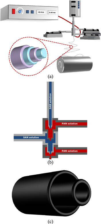
Figure 1. Schematic illustration of the quadruple coaxial electrospinning system. (a) Overall configuration of the coaxial electrospinning setup, (b) sequence of fluid supplied for manufacturing tetra-layered nanofibers and the configuration of the nozzles (so-called core-cut nozzle, where the inner nozzles are retracted inside the adjacent outer nozzle), and (c) a double-tubular CNF fabricated by subsequent thermal treatments.
Download figure:
Standard image High-resolution imageThe coaxial tetra-layered (SAN/PAN/SAN/PAN) nanofibers were then thermally treated to remove the SAN components and carbonize the PAN components, producing double-tubular CNFs (see figure 1(c)). The oxidative stabilization of PAN was carried out at 270–300 °C for 1 h under an air atmosphere, and the carbonization process was conducted at 1000 °C for 1 h under a N2 atmosphere [22]. The ramping rates before the stabilization and carbonization were set to 10 °C min–1.
The morphologies of the electrospun nanofibers were investigated using a field-emission scanning electron microscope (FE-SEM) (JSM-6700F, Jeol). The carbonized microstructures were investigated using Raman spectroscopy (Ar laser, wavelength: 514 nm, T64000, HORIBA), wide-angle x-ray diffraction (WAXD) (wavelength: 0.154 nm, GADDS, Bruker), and high-resolution transmission electron microscopy (HR-TEM, JEM-3000F). The porous structure of double-tubular CNFs was evaluated using the Brunauer–Emmett–Teller (BET, Micromeritics ASAP2420) test.
3. Results and discussion
3.1. Fabrication of tetra-layered nanofibers
There are many parameters to be considered for the successful design of a multi-layered coaxial electrospinning system, such as material compositions of two or more solutions, sufficient applied voltage, optimal flow rates of each solution, and coaxial nozzle shape. PAN/DMF and SAN/DMF were chosen as the material compositions due to their mutual compatibility and immiscibility; additionally, these solutions have been used successfully to manufacture bi- and tri-layered nanofibers via coaxial electrospinning [20, 26]. The applied voltage was empirically determined as the lowest value that can form uniform, multi-layered nanofibers. The flow rates were determined by considering the coaxial electrospinning mechanism; i.e., the outer solution requires a higher flow rate than the inner solution because the inner fluid is produced within the nanofiber by the viscous dragging of the outer solution [26]. The quadruple coaxial nozzle system was empirically designed using a core-cut nozzle concept (see figure 1 for detailed description of the nozzle). The end of the inner nozzle was retracted inside the adjacent outer nozzle, which was proven effective for reducing the jet instability and forming the core/shell structure due to sufficient transfer of the shear dragging force to the inner solution [36].
The SEM and TEM images of as-spun tetra-layered nanofibers are presented in figures 2(a) and (b). Figure 2(a) shows that the nanofibers were uniformly prepared and their average diameter was measured as 1461.7 nm (±184.6 nm). At a glance, the multi-layered structure shown in figure 2(b) is not clear due to indistinct boundaries between PAN and SAN. To observe the unclear boundaries between the layers, SAN components in the nanofibers were selectively removed using acetone. Note that the acetone selectively dissolved the SAN in the nanofibers. Consequently, the boundaries of PAN became obvious (figure 2(c)), confirming that the multi-layered nanofibers, with a perfect interface between layers, were manufactured successfully by the quadruple coaxial electrospinning process. The inner PAN nanofiber did not appear to be concentrically centered, because the SAN components had been removed in the third layers; i.e., the inner PAN layer had not been supported and thus leaned towards the outer PAN layer.
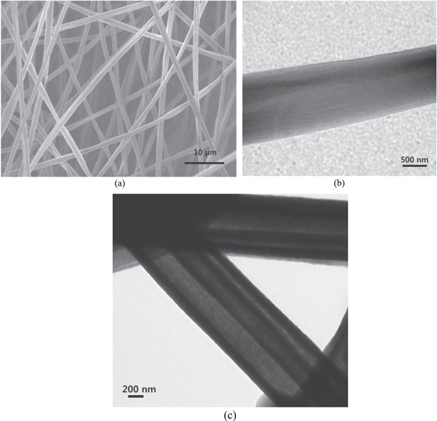
Figure 2. Electron microscopy images of the tetra-layered nanofibers: (a) SEM of as-spun tetra-layered nanofiber mat, and TEM of (b) as-spun and (c) selectively dissolved tetra-layered nanofibers.
Download figure:
Standard image High-resolution image3.2. Morphologies and microstructures of double-tubular CNFs
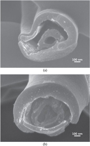
Double-tubular CNFs were uniformly manufactured by heat treatment of concentrical tetra-layered SAN/PAN/SAN/PAN nanofibers (see figure 3(a)). Their morphology and microstructure were systematically investigated. Figures 3(b)–(d) shows typical cross-sections of double-tubular CNFs. The average outer diameters of the inner and outer tubes were 419.1 nm (±87.6 nm) and 767.3 nm (±98.3 nm), respectively. The ratio of the measured diameter of the inner and outer tubes was 1:1.83, which differed slightly from the target ratio (1 : 2). This was probably due to excess stretching of the outermost PAN layer during coaxial electrospinning [26]. The measured wall thickness ratio of the two tubes was 1:1.46, which was also different from the target ratio (1:2.14). The wall thicknesses of the inner and outer tubes were 53.8 nm (±14.3 nm) and 78.3 nm (±29.6 nm), respectively. The average eccentricities of the inner and outer tubes (eccentricity: (1 − b2/a2)1/2, where a and b are the lengths of major and minor axes on the ellipse [20]) are 0.689 (±0.065) and 0.251 (±0.093). The cross-section of the outer tube was more circular than that of the inner tube; a smaller eccentricity indicates a more circular shape [20]. Based on the morphologies discussed so far, the shapes of the tubes in the double-tubular CNFs were a result of the coaxial electrospinning mechanism, i.e., the more circular shape of the outer tube was attributed to the uniform charge distribution, while the oval shape of the inner tube resulted from unbalanced shear dragging by the outer fluid.
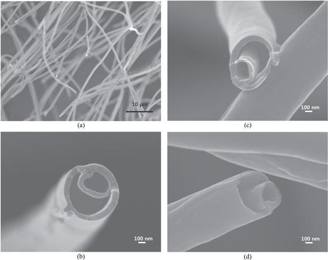
Figure 3. Typical FE-SEM images of the carbonized tetra-layered nanofibers: (a) low-magnification double-tubular CNF mat, and (b)–(d) high-magnification images of double-tubular CNFs.
Download figure:
Standard image High-resolution imageThe microstructures of double-tubular CNFs were investigated by WAXD and Raman spectroscopy. The WAXD curve shows representative peaks of the turbostratic carbon crystals: primary ((002) at 2θ = 24.12°), secondary ((10) at 43.47°), and tertiary ((110) at 81.11°) peaks [21] (see figure 4(a)). A slight peak of (004) was also observed near 52.95°. For a more detailed analysis, the WAXD curve was deconvoluted using Gaussian peak functions. The (002) peak related to the turbostratic carbon was centered at 24.61° (note that the slightly upshifted (002) peak center of the deconvoluted peak resulted from subtraction of the rare-carbonized fraction), and d002 was calculated as 0.361 nm using Bragg's equation. It is noteworthy that the peaks around 19.23° and 32.32° are mainly related to the incomplete carbonization of the PAN molecules [37]. The Raman spectrum in figure 4(b) also indicates the successful formation of the turbostratic carbon structure. The primary peak near 1380 cm–1 (D-peak) is related to structural disorders in the graphitic layers (i.e., diamond-like carbon), while the secondary peak near 1583 cm–1 (G-peak) represents the in-plane tangential stretch vibrational mode (E2g) of the graphitic layer [20]. The Raman spectrum was also deconvoluted using Gaussian peak functions to calculate the integrated area ratio (ID/IG ratio). The ratio was 1.61, which is higher than that of the hollow CNFs thermally treated under the same conditions [21], implying a higher fraction of the disordered carbon structure. The less-ordered turbostratic carbon is attributed to the coaxial electrospinning process; i.e., the PAN molecules in the outermost layer were not fully stretched and recrystallized due to the resistance of the inner layer upon shear dragging, whereas the PAN molecules in the second layer from the center did not reorganize to the same degree because of shear dragging. The microstructure of carbonaceous materials strongly depends on the heat treatment temperature; thus, the microstructure of double-tubular CNFs will improve with a higher carbonization temperature or longer thermal treatment time.

Figure 4. (a) WAXD curve and (b) Raman spectrum of the double-tubular CNFs.
Download figure:
Standard image High-resolution imageThe microstructure of the double-tubular CNFs was further investigated by HR-TEM. As shown in figures 5(a) and (b), the carbonaceous crystallites of the outer tube were much more developed than those of the inner tube. The carbonaceous crystallite size (La) of the outer tube (6.5 nm (±1.0 nm)) was significantly larger than that of the inner tube (4.4 nm (±1.7 nm)). The crystallite thickness (Lc, the number of carbon layers) of the outer tube (5.0 (±1.1)) was much greater than that of the inner tube (3.8 (±0.8)). To determine the degree of carbonization of the outer and inner tubes, the interlayer spacing values between the (002) planes (i.e., d002) were carefully measured. The outer tube shows better crystallographic quality: the interlayer spacing of the outer tube was in the range of 0.35–0.43 nm, more compact than the inner tube (0.35–0.50 nm) (see figure 5(c)). Overall, the carbonaceous crystallites of the outer tube were significantly well developed compared to those of the inner tube due to the different stretching mechanism [26].
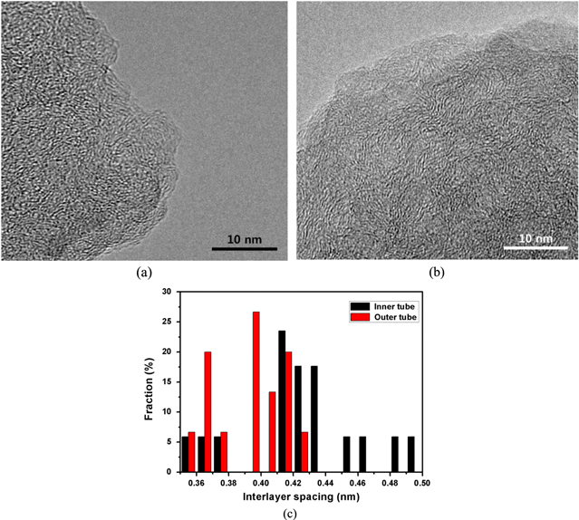
Figure 5. HR-TEM images of the double-tubular CNFs. (a) Inner and (b) outer tubes and (c) interlayer spacing distribution of the carbonaceous crystallites of the outer and inner tube in double-tubular CNFs.
Download figure:
Standard image High-resolution image3.3. Porous structures and variants of double-tubular CNFs
The CNFs derived from PAN nanofibers through the carbonization process possess turbostratic carbon crystallites, non-crystalline carbons, and micro- or meso-pores [25]. In addition to crystal structure, the pore size and distribution of CNFs are among the most important parameters that affect microstructure and potential applications. The surface area and pore distributions of the double-tubular CNFs were characterized by BET and compared with those of hollow carbon nanofibers (HCNFs) and porous hollow carbon nanofibers (pHCNFs), which were prepared under the same heat treatment conditions reported in our previous work [22]. The BET surface area of the double-tubular CNFs was 50.04 m2 g–1, much larger than that of the HCNFs (13.18 m2 g–1) and pHCNFs (13.32 m2 g–1). The increased BET surface area of the double-tubular CNFs compared to those of HCNFs and pHCNFs was attributed to the introduction of the inner tube and the decreased overall diameter and wall thicknesses. The total pore volume of double-tubular CNFs was 0.040 95 cm3 g–1, larger than those of the HCNFs (0.027 46 cm3 g–1) and pHCNFs (0.039 15 cm3 g–1). In contrast, their average pore size was 3.27 nm, much smaller than those of the HCNFs (8.33 nm) and pHCNFs (11.76 nm). The nitrogen adsorption isotherm of the double-tubular CNFs in figure 6(a) shows the typical Type III (non-porous carbon) isotherm according to IUPAC classification [38]. The pore volume of micro-pores (0.105 cm3 g–1) in the double-tubular CNFs was much higher than those of the HCNFs (0.038 cm3 g–1) and pHCNFs (0.021 cm3 g–1) (see figure 6(b)). Basically, micro-pores in the double-tubular CNFs originated from the microstructural evolution of PAN. It is well-known that the oxidative stabilization and carbonization of the PAN nanofibers usually accompany the release of NH3, HCN, N2 gases, etc, resulting in the formation of the micro-pores within the carbon fiber structure [39]. The increased micro-pores of double tubular CNFs can be attributed to the better crystallized microstructure [39]. Note that the outer tubes of the double-tubular CNFs showed the more developed crystalline structures compared to the HCNFs: the crystallite thickness (Lc, the number of carbon layers) of the outer tube (5.0 (±1.1)) was higher than that of the HCNFs (4.6 (±0.8)), while the carbonaceous crystallite size (La) of the outer tube (6.5 nm (±1.0 nm)) was significantly larger than that of the inner tube (4.5 nm (±0.9 nm)) [21]. Therefore, the more developed microstructure of the outer tubes brought about the increased micro-pore volume. On the other hand, the micro-pore volume was also affected by the release of the thermally decomposed SAN molecules. The micro-pore volume of the double-tubular CNFs was increased due to increased relative SAN/PAN ratio (0.225/0.250) compared to that of HCNFs (0.150/0.200) and the penetration of thermally decomposed SAN molecules in the innermost layer into both inner and outer tubes. In brief, the increased micro-pore volume resulted from the microstructural change of PAN and the increased effect of the thermally decomposed SAN molecules. Note that the low micro-pore volume of the pHCNFs (0.021 cm3 g–1) resulted from the pore coalition mechanism [22]. The large surface area and pore volume of the double-tubular CNFs make them interesting potential materials for electrodes of supercapacitors or cathodes of Li–Air batteries.
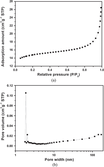
Figure 6. (a) Nitrogen adsorption isotherm of the double-tubular CNFs and (b) their pore size distribution (BJH desorption pore volume).
Download figure:
Standard image High-resolution imageLastly, double-tubular CNFs were prepared with nanoparticles located between their tubes to demonstrate the potential variants of double-tubular CNFs. Aluminum acetate (Al-ac, Sigma Aldrich) was incorporated between tubes of double-tubular CNFs. The PAN and SAN solutions had the same configuration explained in section 2, except Al-ac (60 wt% SAN) was dissolved in the third SAN layer. The same electrospinning and heat-treatment conditions used for the previous double-tubular CNFs were employed. Figures 7(a)–(b) clearly shows double-tubular nanofibers, the inner tubes of which were perfectly separated from the adjacent outer tubes. The double-tubular structure is shown in figure 3; however, the inner tubes appear to be conjoined with the outer tube. This unified structure was likely formed during heat treatment because SAN layers were released, rendering the inner tube unsupported unless it leaned on the outer tube. The inner and outer tubes were then bonded for the subsequent carbonization process. Al-ac dissolved in the SAN layer between the two tubes prevented the inner tube from touching the outer tube, floating it within the outer tube as shown in figure 7. This method can be extended to manufacture multi-functional double-tubular CNFs having two concentrically arranged cylindrical channels; the same or different functional materials can be incorporated into these channels.
Figure 7. FE-SEM images of alumina nanoparticles incorporated double-tubular CNFs. (a) and (b) are arbitrarily selected images of the nanofibers manufactured using the same electrospinning conditions.
Download figure:
Standard image High-resolution image
4. Conclusions
Concentrical tetra-layered SAN/PAN/SAN/PAN nanofibers were successfully manufactured using a quadruple coaxial electrospinning process. Through subsequent heat treatment, the tetra-layered nanofibers were converted to double-tubular (or tube-in-tube) CNFs. The mechanism behind the multi-layered nanofiber formation during coaxial electrospinning was determined. The outer tube of the double-tubular CNFs was stretched to a greater degree by electrical forces, whereas the inner tubes were shear-dragged by the outer fluid, resulting in denser carbon crystals in the outer tube than the inner tube. The BET surface area (50.04 m2 g–1) and total pore volume (0.040 95 cm3 g–1) of double-tubular CNFs, which were likely formed during the thermal treatment process due to the release of thermally decomposed SAN molecules, suggests the presence of a great number of micro-pores in the CNFs. Lastly, double-tubular CNFs with foreign materials incorporated between their tubes were prepared, demonstrating that the inner tube of double-tubular CNFs can be floated within the outer tube and multi-functional materials can be readily incorporated into those concentrical cylindrical channels.
Acknowledgment
This work was supported by the Mid-career Researcher Program (2013R1A2A2A01067717) through an NRF grant funded by the MEST.