

Introduction: Another Cardboard Robot-vacuum-cleaner Controlled With Arduino


This is simple robot-vacuum-cleaner controlled by Arduino.
This can be even simpler if instead of turbine and dust-bin - use a kitchen tissue or a piece of synthetic fabric.
Step 1: Required Components

- Arduino
- Motor-shield - controls motors. Also known as H-Bridge. Here motor-shield is YFRobot with L298P. Therae are other models with are controlled with different contacts (like this).
- Two motors with gears and power wires.Motor with gears has 100-200 RPM (revolutions per minute). It is good to connect ceramic capacitor 1uF to motor power contacts - to reduce electric noise.
- Two wheels
- Battery set, or accumulator, or power-bank - on 5 volts
Computer cooling turbine on 5 volts. Or on 12 volts - but this require additional 12 volt power or step-up converter 5 volts to 12 volts. A turbine can be found on ebay: "cooling blower fan 5V".
- A set of strong magnets
Wires to connect to battery set. Or USB cable - to connect to power-bank with USB power connector.
Cable with power connector for Arduino
- Wires for Arduino contacts (breadboard wires)
- Cardboard
- Glue or melting glue
- Piece of tin (e.g. from aluminum can)
- Plastic box - for dust-bin
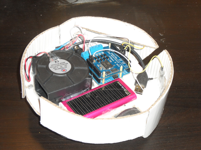
Step 2: Arrange Components on Chassis

Cut the circle from cardboard - chassis of the robot, arrange components on it.
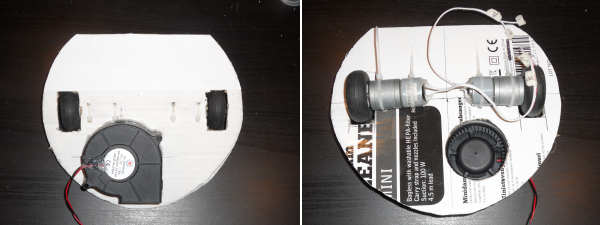
Step 3: Setup Motors

Setup the motors (with gears) and wheels on it - cut out holes for wheels and secure motors on cardboard with ropes, wires or plastic ties.
Step 4: Setup Turbine
Cut the round hole in the chassis for turbine and glue the turbine on the chassis.
Step 5: Turbine and Motors

Turbine is on top of the chassis, motors - below it.
Step 6: Prepare to Set Dust-bin

Mark the place where the plastic box will be fixed - this will be a dust-bin. Pin holes around where the magnets will be located on the top side of the chassis.
Step 7: Fix Magnets

On the top side of the chassis Glue magnets using hols pinned on the previous step as marks.
Step 8: Fix Dast-bin


Put a piece of paper on the place where the dust-bin will be set.
Put the plastic box on top of this paper - this will protect the box to be glued to chassis!
Put magnets around the plastic box. Magnets will stick on the places above magnets glued on the top side - holding the paper below the box.
Fix magnets to the box with glue. When the glue dries - the box will be hold on the chassis by magnets and it can be removed.
Cut away the paper.
Step 9: Fix Arduino Holders

Wooden stick are fixed with glue so Arduino board can be put on these sticks.
Or use another way to fix the Arduino board with motor-shield.
Step 10: Prepare Power Wire

Use wire to connect to the battery set.
Or use USB wire to connect to a power-bank.
Be careful
- wrong polarity will destroy Arduino and motor-shield
- shorting of power wires will destroy batteries or power-bank
Step 11: Connect Power Wires

Connect all power wires from Arduino, turbine, motor-shield and battery-set.
Be careful
- wrong polarity will destroy Arduino and motor-shield
- shorting of power wires will destroy batteries or power-bank
Check before power on.
Step 12: Make Bumpers

Bumpers are made from the cardboard stripes. They bended and glued in such shape.
Step 13: Setup Bumpers


Bumpers are fixed on the chassis in the way so when they are hit - they bend a bit hitting the chassis.
Chassis is cut a bit if it is needed some space till bumpers.
Step 14: Contacts for Bumper

Clean and scratch tin and wires for better contacts. Pieces of tin are connected to wires and fixed by glue. Be sure the glue is not put between tin and wires.
Step 15: Connect Bumpers

Fix contacts from tin to bumpers with glue - connect them to Arduino inputs (e.g. pins 5 and 8).
Another wires (with contacts on its end) are fixed in-front of such contacts on chassis. Connect these two wires to Arduino GND.
When the bumper is pushed (e.g. it hits the wall) - contacts are connected, a pin gets connected to GND.
No resistors needed - internal pullup Arduino resisters are configured in program.
Step 16: Setup Filter

A piece of synthetic fabric is used as a filter.
Step 17: Rear Support


A plastic or cork is used as a rear support - it is fixed on the box by glue.
The shape or location is fixed in the way that the box is 1 mm above the floor - when the robot is on its wheels.
The thin hole in the box is where the air comes with dust from the floor.
If the box is too high - cut walls and re-glue magnets.
Step 18: Program

The program on github
Step 19: More Details About Connections

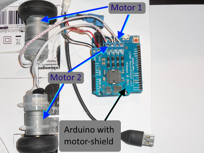


Some details about interconnections.
Motor-shield mounted on-top of Arduino board.
Turbine, Arduino and motor-shield are connected to battery by power wires (or a power-bank via USB cable).
Be careful with polarity - wrong polarity will destroy Arduino and motor-shield!
Step 20: Using Arduino Nano


Motor-shield can be connected to the Arduino board with wires. Just connect following contacts between Arduino and motor-shield: 3, 4, 5, 6, 7, 8, GND, +5V
in the way:
pin GND Arduino is connected to pin GND on motor-shield,
pin 5V Arduino is connected to pin 5V on motor-shield,
pin 3 Arduino is connected to pin 3 on motor-shield,
pin 4 Arduino is connected to pin 4 on motor-shield,
etc.
So it's possible to use such board as Arduino Nano - which is smaller than motor-shield.
Step 21: Using Motor-driver HG7881

The motor-driver on HG7881 can be connected to Arduino by wires. It is much cheaper than motor-shield but maximum current is 800mA - which should be enough for most small DIY robots.
The program is a bit different: github


