555SS_diagram

The LDR Synth is a light-to-sound noisemaker built with relatively common components. As the name would imply this project uses a Light-Dependent Resistor – LDR, commonly referred to as a photoresistor – in combination with the venerable 555 timer to produce rapid pulses that output as a pitch range through an 8Ω mini speaker.

The 555 itself is a tiny integrated circuit – IC – that looks like a little bug. It’s assembled in this 8-pin dual in-line package configuration:

555-tiny

Believe it or not that little guy can be found in everything from modern toys to yesteryear’s windshield wipers. Even today it is estimated a billion of these ICs are manufactured annually.

You can read up on the theory, background, and fundamentals of the 555 timer in Charles Platt’s Make: Electronics book, pp. 150–161, available from the Maker Shed or from your local RadioShack store. Additional links to resources I commonly scour for knowledge of the 555 timer and projects built with it are available at the end of this project guide.

We’ll be operating the 555 timer in astable mode, which basically means it emits one pulse at a time. Take a look at the simplified diagram below to see what is going on inside the 555 timer as it relates to this circuit:

Inside the 555 timer, from Charles Platt's book Make: Electronics, p. 158.
Inside the 555 timer, from Charles Platt’s book Make: Electronics, p. 158.

As noted the astable 555 will emit pulses. The duration of that pulse, or rather the space between pulses, is typically determined by the values of a resistor between pins 7 & 8 that connects to VCC, and a capacitor between pin 6 and GND. While this is essentially true with this circuit (see schematic below), the value of that resistor (the photoresistor) will vary in relation to the amount of light being shined upon it. Thus when there is less light, there is more resistance, and the duration between the pulses increases, emitting a deeper pitch tone. When there is more light, there is less resistance, and the duration between pulses decreases, emitting a higher pitch tone.

Here’s the circuit schematic:

555SS_schematic

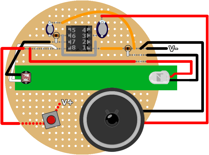
The capacitor between pin 6 and GND also controls the timing of the pulses emitted by the 555. In the schematic above I’ve listed a 2.2μF electrolytic capacitor, but you can adjust the value of this component. Thus I highly recommend you breadboard your circuit first, so you can experiment with the LDR and the value of this capacitor. Your layout should look something like this:

555SS_bboard

Changing the capacitor on the top side of this breadboard layout produces the following audible results. Because the amount of light hitting the LDR was quite low, in a controlled, dark setting, the sounds you hear are emitted as clicks. This will not be the case when the light from the LED is shined upon the LDR, as you’ll hear later.

So you can imagine even with a high-brightness LED, the 6.7μF capacitor will produce a deeper tone than the 2.2μF. In my experiments I found that anything outside of those ranges was either too high-pitched to be tolerable or too slow to be substantial. But play around with the setup and choose the configuration that works for you. I eventually opted for the 2.2μF capacitor given the brightness of my LED and the light properties of the material I chose for the tube.

DSC00442

I sourced this green tube from a 99¢ store. It was the shaft of a bouquet of synthetic flowers. The armature holding one of the flower’s stems was also sourced for the metal rod used to slide the LED in and out of the tube like so:

slinthtarGIF3_500px_wrep

Which at full brightness produces a sliding range of sounds like this:

And like that we can turn light into sound!

Watch the following video to get another snapshot of how it all comes together, and follow the steps below to build your own LDR Synth. I’ve included some notes in the conclusion about further modifying this project, and I’d like to see any ideas you come up with.

This project is inspired by the 555 Slider Synth by Dino Segovis. I am indebted to Dino for this and other Hack A Week projects and ideas.


Project Steps

Breadboard the Circuit

I really can’t recommend this step enough. You’ll want to breadboard your circuit to both experiment with the value of C1 and also to ensure the LED/LDR combo is the one you want.

TIP: The five LDRs that come in RadioShack #276-1657 Photoresistors (5-Pack) all have different resistance values. You can find the datasheet for those components here. I did not find that datasheet until after I soldered my project. I chose a ‘medium’ sized LDR from that pack for my build.

NOTE: The speaker package shown in the illustration and in the image of the breadboard layout is a mini buzzer, which works fine for prototyping. But to get the full impact synth sound you’ll want to use the 8Ω mini speaker specified in the parts list and shown later on.

Drill the Switch Hole

From the round PCB kit, choose the largest available PCB.

Prior to laying out the circuit in Fritzing I made a few drawings of where I wanted all the components. I wanted to give the switch ample room, to accommodate people with larger thumbs. I experimented on scrap pieces of perfboard drilling a hole for the momentary pushbutton switch. I eventually settled on the location seen in image 1 for the switch listed in the parts above.

If you have a 13/64″ drill bit, the hole should be just right. If you only have a more-common 3/16″ drill bit, you’ll need to drill out slightly more room, or you’ll struggle with inserting the switch later.

NOTE: The green tube is a scrap piece of the tubing from the fake flower bouquet. I only taped it here as reference.

Solder the IC socket

NOTE: This is very important before proceeding. In my layout, note the IC socket is mounted with the notch facing south (image 1). This would mean the 555’s pin 1 will be located in the bottom-right. I oriented the socket in this way to adjust for where the other components would connect.

Mount the 8-pin IC socket to the perfboard at the shown location. Count the number of holes and refer to the diagram in the introduction above to verify.

Tape the socket to the perfboard to ensure it won’t fall out while soldering the pins.

Flip the perfboard over and using a pair of helping hands, vice, or your preferred method, solder the socket’s pins to the perfboard. The socket will be your reference point for all the other components and wires.

Begin Soldering the Circuit

You’ll notice I have turned my resistors ‘on end.’ I prefer my resistors to lay flat but wanted a dense layout for this project so they are upright like shown. Both of these resistors are 100Ω 1/4W 5% so their color-coding is brown-black-brown with a gold stripe.

The stripe on these electrolytic capacitors indicates their negative lead. Double-check the orientation of your capacitors before soldering them in place.

In image 1, note the grey wire connecting pin 2 (on the right side of the socket) to pin 6 (on the left side of the socket).

In image 2, the red wire shown is not yet soldered, but everything else is. I then trimmed this red wire down so the left side of the wire aligned with pin 8 of the socket. See the diagram in the introduction above to verify.

The scrap piece of green tubing at this point is simply taped to the perfboard to verify my component layout won’t conflict with the tubing. With that in mind I used a pencil and traced along the edges of the tubing, before proceeding to the next step.

Solder the Mini Speaker

With the ‘north side’ of the perfboard layout populated, and with the pencil marks indicating the width of the tubing, I located the mini speaker as shown. The speaker’s red (+) wire connects with the negative (-) lead of the larger capacitor (100μF), while the speaker’s black (-) wire connects where shown, aligning with the row of the socket’s pin 1. The orange wire between pin 1 and the resistor “jumps” this connection.

Place a small drop of hot glue to the underside of the mini speaker and secure it in place.

Prepare the LDR

Cut, strip, and tin the ends of two lengths of wire. I chose 24AWG because it is slightly less-stiff than 22AWG, and RadioShack sold a roll of intercom wire that comes in 4 colors for me to choose from. For the LDR I chose black and white. Since this is a resistor of sorts, there is no polarity, so the leads are not positive or negative as with most components.

I trimmed the leads of the LDR as shown in image 1.

With the wires soldered to the LDR’s leads, slip two lengths of heat-shrink tubing over the connections and apply heat from a heat gun or lighter to shrink the tubing. You now have a nicely prepared LDR for inserting in your synth’s light tube!

Hot Glue the LDR in Place

At this point I removed the scrap tubing from the perfboard and located the actual light tube I would be using for this project. As seen in the introduction above, I chose this tubing because when the LED is illuminated you can partially see the light inside the tube. Alternatively you could use a more opaque tube, but I don’t recommend a clear tube because it will let more light in. My light tube’s length is 6″.

CAUTION! The last thing you want to do is get hot glue or any epoxy on the top of the LDR. This is the light-sensitive part of the component. Just be patient and ensure you don’t make a mistake that you can’t undo.

I located where I wanted my LDR to rest in the light tube, then I carefully applied hot glue to hold the LDR and wires in place.

With the LDR secured in place, I twisted my wires and cut them to the length needed to align with pins 7 & 8 on the left side of the socket (image 3). The green tubing is simply resting in place, but we’re about to secure it.

Glue the Light Tube in Place

From the earlier-drawn pencil marks, I knew where I would secure the light tube in place. Dispense enough hot glue to ensure the tube will be held in place, and secure it.

On the underside of the perfboard, you’ll notice some divots of glue might push their way through. Smooth them down, especially in the middle where the battery holder will be secured.

You should have an instrument that looks similar to image 3. All that remains are the battery holder, switch, and LED.

Secure the Battery Holder

I held the battery holder in place, approximately in the middle, and used a marker (or pencil) to outline the perimeter of the holder.

In image 2 you can see hot glue being used to secure the holder. DON’T USE HOT GLUE! Later, the battery holder snapped off the hot glue. Use double-sided foam tape instead. It is much stronger for this application.

Insert the Switch & Solder the Battery Connector

The reason I drilled out the switch hole earlier was so that I wouldn’t be drilling the perfboard with components already mounted to it!

Solder the battery snap connector’s black (-) wire to the right of the speaker’s black (-) wire.

Insert the momentary switch. I used two pairs of pliers to secure the switch body and nut in place. One plier is used to hold the switch body while the other tightens down the nut from above. Solder the contacts as shown in the circuit & diagram. The battery snap connector’s red (+) wire will get soldered to one of the switch contacts, while the other switch contact will get soldered to align with pin 8.

TIP: Image 3 shows how I wired the switch. I used small lengths of heat-shrink tubing over the switch contacts to protect the contacts. The red and black do not indicate polarity, But you should use heat-shrink tubing to protect leads like this. Remember you’ll always need to slide the heat-shrink tubing over the wire before you solder the connection!

NOTE: You’ll note in image 2 the LED’s wires are already soldered to the perfboard. Proceed to the next step for a word of advice before making this connection, but it will eventually get soldered where shown.

And of course now you can insert the 555 timer in the IC socket. Remember, for this circuit design, this 555’s “dimple” on the package will be located in the bottom-right, with the perfboard in the orientation shown. Again refer to the diagram in the introduction to verify.

The LED

I greatly underestimated the length of wires needed to connect the LED with the perfboard. My original lengths of wire were around 12″. This caused me to be unable to fully slide the LED out of the tube. Instead of de-soldering the perfboard connection I decided to cut the wires and increase their length by soldering and shrink-tubing two additional lengths of wire. Thus I have red & black wires connecting to the perfboard, but green & white connecting to the LED. (Obviously for continuity I should have just used red & black wire – I don’t know why I didn’t actually.)

Don’t be confused like I was when I first cut my lengths of wire! With a 6″ light tube, I eventually needed ~24″ of wire to go from the LED to the perfboard, to account for a comfortable length of slack needed while playing the LDR Synth.

I wound the wires around the thin metal rod to make the whole thing more rigid and stiff.

Your Light2Sound LDR Synth should resemble something similar to image 3!

Verify All The Connections

Before powering up your LDR Synth, verify all the connections, and once again confirm the orientation of the 555 timer IC. Refer to the full-layout diagram at the beginning of this project’s introduction. All of the grey dots seen indicate connections across those rows and columns between components and wires as indicated.

When you’re ready, connect the snap connector to the battery and depress the momentary switch.

Get Ready to Rock!

Try playing your favorite NES tune, or a recent pop hit with your newly made LDR Synth.

Record your tunes and upload them online for all to hear! Share a link in the comments below so others can hear your synth skills in action.

Conclusion

Like a next-level Light Theremin, the Light2Sound LDR Synth is fun to both make and play. But it could easily be taken to the next level!

It wasn't until after I finished building the project that I considered using small PC board terminals to change out the lower value capacitor (C1). This way you could somewhat easily change the pitch range of the instrument by changing just this one component.

The output of the unit could also be sent through an amplifier, such as a MonoBox Powered Speaker.

Again thanks to Dino Segovis at Hack A Week for this project inspiration. And I also recommend Electronics Club (formerly kpsec.freeuk.com) by John Hewes which has some great 555 tutorials and knowledge.