

Introduction: Lesson 2: Using Arduino As a Power Source for a Circuit


Hello again, students, to my second lesson of my course to teach basic electronics. For those who have not seen my first lesson, which describes the very, very, basics of circuitry, please see that now. For those who already have seen my previous lesson, let us begin.
Step 1: What Is Arduino?
To start off this lesson, let us start with asking: what is this strange blue device you see on your screen? The answer is an arduino.
I will define to you what Arduino is in a single statement: Arduino is a chip which is the master and manipulator of all circuits that connect to it. This seemingly simple chip is the very basis of several complex projects constructed world-wide, and yet is simple enough to program that even children can easily learn how to use it.
Okay, okay, before you start breaking a sweat about not knowing what half of what I will say will mean, just know that today's lesson is just comparing certain parts of Arduino with that of a basic circuit. Don't worry, I am not eating any steps here.
Step 2: Arduino Vs a Basic Circuit

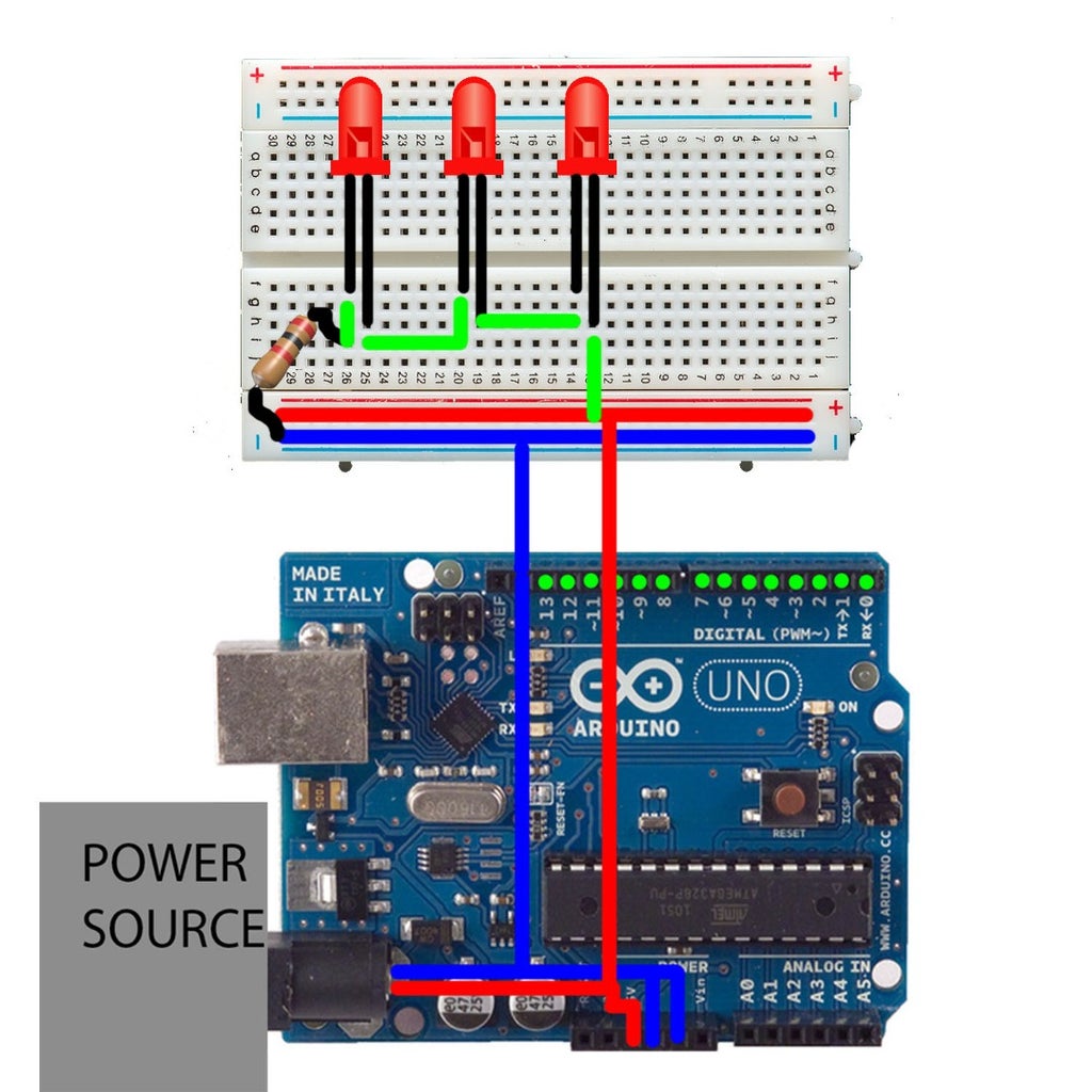
For those who have seen my previous lesson, this color coded version of the diagram should seem familiar. Red represents power, blue the ground and green are pins that are connected to a power. The Grey box seen above the Arduino is a power source or battery of any kind.
However, this lesson will not focus on the green pins coming from the Arduino. Instead, we will be focusing on doing what we did in the last lesson (which was lighting up an LED), except we will be using an Arduino as a power source.
Step 3: Materials for Making Your Arduino-Powered Circuit


When beginning to construct your new circuit you will need the following things:
-1 Arduino Uno
-1 Battery to plug into the Arduino
-1 Half sized bread board
-Any number (though prefferable 1-3) of LEDs
-A resistor(of any kind)
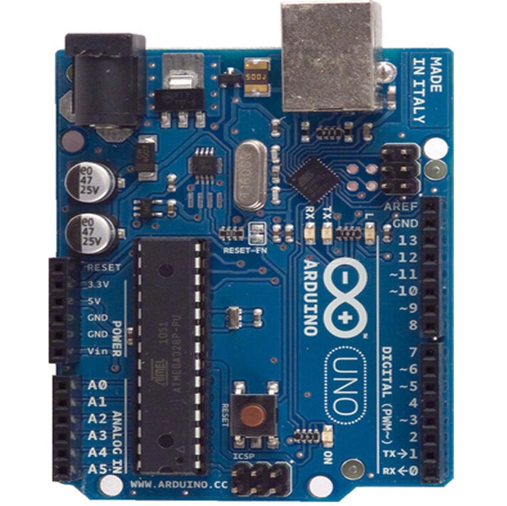
Before you make your connections, I would like to bring up some details about which pins from the Arduino Uno to use. Looking at the regular diagram of the Arduino, you should see 2 important names: 5V and gnd. These are what you will be using as your power and ground terminals. 5V is the name of the pin you will be using for power. Gnd is an abbreviation for ground, so use any of the three pins on Arduino labeled gnd as your ground.
Also, for some electrical safety, be sure to know the following: The LEDs you see on the diagram of your list of components have an observable feature: one leg is longer than the other. When connecting LEDs in circuits, make sure that the longer leg is connected to the power side and the shorter leg to the ground side. If you switch the legs, your circuit will not work.
Step 4: Making the Connections...
For making your connections, follow the following steps:
-For power and ground, use wires to connect them to the horizontal long rails. For the power, connect the wire anywhere on the horizontal red rail (the rails are labeled, red being power and blue being ground) and for ground, connect a wire from it to anywhere on the blue rail.
-From the power rail, add a wire, connecting the power to the long leg of the first LED*.
-(if you are only doing one led) use a wire to connect the short leg of the LED to the ground. Your one LED should light up brilliantly.
OR....
-(if you are connectng more than 1 LED) use a wire to connect the short leg of the first LED to the long leg of the second LED. This works because the electricity flowing out of the short end of the first LED is almost like as if the first LED is an extension of the Power rail. But, like connecting the first LED, this electricity has to go to the long leg of the second LED, or else the circuit won't be complete. Repeat this procedure until you are on the last LED.
-When you are on the last LED, connect the last LED's short leg to any end of the resistor and connect the resistor's second end to the ground rail.
And then you have an Arduino powered LED circuit!! Yippee!!!!
*When connecting wires on any of the non-power or ground-related rows, make sure your connections between the power or ground to the LEDs are ON THE SAME COLUMN, as seen on the diagram, otherwise the electricity won't flow. Those who've seen the previous lesson, you know exactly what to do.
Step 5: Your Circuit in a Complete Circuit Diagram

Since the previous diagram might be a little bit confusing to some, I've taken the time to make a diagram in the format you all know and love. In simple terms, the 5V pin (the power) connects to the long end of the first LED, which connects its short leg to the long leg of the second LED, which does the same for the third LED. The third LED, then connects it's short leg to the resistor (which allows the electricity to flow without burning the LEDs) which then connects to the Arduino's gnd. Being that the LEDs are directly connected to the Arduino which is hooked up to a battery, they all should light up!
Now you have mastered the idea of using an arduino as a power source to directly give electricity to your circuit. Achievement unlocked!
Step 6: Next Time...
Next time on GearsnGenes' tutorial series, you will learn to manipulate your circuit, allowing it to do more than just be a constantly shining LED. Enter the coding proccess! Until next time, pupils!


