
The clinical practice of endodontics is subject to some paradoxes. One of these paradoxes involves examining the apical extent in order to evaluate root canal debridement and filling. The conventional assessment method evaluates the result of the endodontic treatment by the apical position of its obturation, even though it has been proven that the location of the apical foramen is not invariably located at the root apex.1 Despite this knowledge, the majority of practitioners still routinely use this location to determine the final quality of an endodontic treatment. They focus attention on the apical region with the certainty that their examination will obtain pertinent information regarding the periapical tissues.
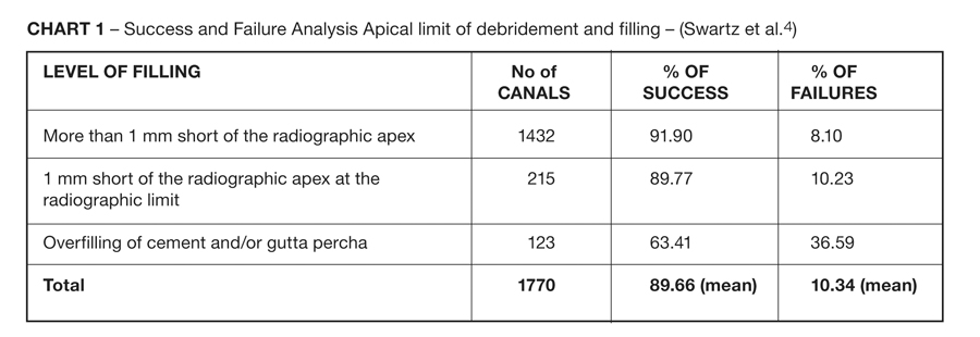
Although partially true, this belief that the success of endodontic treatment is linked to the apical location of its filling shows the importance of correctly identifying and maintaining the working length in endodontic treatment (Chart 1). Determining the working length is one of the first steps in endodontic therapy. This step involves measuring the canal length in order to identify the apical limit of debridement.2 This defines the depth to which instruments may penetrate into the root canal and, consequently, the depth at which tissues, impurities, metabolites, and material(s) remain and the depth to which distance other undesirable components need to be removed. The apical limit identifies the depth the canal filling may reach in obturation and, among other factors, affects the level of post-operative comfort or discomfort.3
CHART 1. Success and Failure Analysis Apical limit of debridement and filling – (Swartz et al.4).
The most precise definition conceives the apex as being the anatomic point most distant from the incisal edge or occlusal surface of the tooth5, and the term working length as being the distance between a point of reference located on the coronal aspect and a point of reference at the terminal limit of preparation and root canal filling. There is no general agreement of where the best terminal limit for root canal cleaning, shaping, and obturation procedures is located. Some advocate the apical constriction as the ideal limit, but there are some considerations that must be discussed.
The apical constriction is defined as the narrowest portion of the root canal at the apex. The topography of the constriction has been the subject of many research studies and is controversial to the point that some discussions have questioned its existence. It has also been long disputed whether the apical constriction should be recommended as the end point of root canal treatment. In fact, researchers debated about the ideal apical limit as early as 1929. Clinically and radiographically, locating the apical constriction and foramen is difficult to say the least — nearly unbearable to be more precise. An accurate location of the apical constriction is not possible because anatomic landmarks vary greatly.
The high resolution of micro CT portrays the apical anatomy in detail and offers accurate measurements and location of the constriction and foramen without destruction of the tooth. Anatomic studies using micro CT technology show that the topography of a canal varies with the position of the longitudinal section. They also show that the minor diameter only indicates the narrowest area in perfectly round canals, which rarely exist. The micro CT studies reveal that the apical constriction is in close proximity to the foramen (around an average of 0.2 mm), and the most common form of constriction is the parallel form. The traditional vision of constriction with canal flaring apically and coronally is present in only 10 percent of the canals.
Today, accurate location of the apical major foramen is possible through the use of apex locators. Some clinicians recommend shaping and filling to the major apical foramen to debride the canal to its whole length, advocating debridement and obturation to the foramen, which often results in material being extruded into periradicular tissues. The downside of this recommendation is that this makes it impossible to build an apical stop, which is necessary for keeping the obturation material in a biologic limit. The results of apical limit studies demonstrated that the extrusion of filling materials beyond the radiographic apex correlated with a decreased prognosis. An analysis of the studies suggests – and, biologically, it is rational to recommend – cleaning up to the foramen exit but obturating short of the foramen. This implies cause and effect. In reality, length and success are correlated.
Determining The Working Length (WL)
Several techniques for determining the working length have been scientifically described and assessed. These techniques include digital tactile sense, radiographic methods,6–8 and electronic methods, each used alone or in combination. The use of a combination of techniques, according to some authors,9–11 provides more reliability in determining an apical limit of debridement.
The methods that use radiographic image interpretations have limitations due to factors such as distortions12, anatomic interferences, and objects pertinent to endodontic treatment. There are also restrictions with respect the fact that they are two-dimensional images of three-dimensional objects13, which makes it impossible to visualize the apical foramen and leads to subjective interpretation by the operator.14
Although the radiographic method by Ingle is the most widely used working length technique and has reasonable precision for locating the apical limit, this method has several limitations that tend to diminish its precision and reliability. The primary problem is the difficulty of obtaining a good radiographic image of the tooth being treated. The final quality of the radiograph is linked to several variables, involving the correct positioning of the film with regard to the object to be radiographed, correct angle of the X-ray beam, interferences of anatomic structures or the equipment used to isolate the operating field, exposure time to radiation, and adequate radiographic processing.15
Principles of Electronic Measurement and its Development
The electronic method has been studied and improved since the last half of the 20th century with the aim of improving the precision of the technique. Since the first experiments by Susuki16 and Sunada17, the electronic method has shown appreciable technological advances, overcoming the initial problems particularly in respect to the inability of taking readings in root canals containing irrigation solutions with electrical conductivity. During the last few years, studies assessing the electronic method have resulted in satisfactorily accurate data, indicating that electronic apex locators have found a prominent place in clinical endodontics and endodontic research.
The early devices showed success rates that were lower than or comparable to radiographic techniques. However, when the third generation electronic apex locators were introduced, it was possible to establish the foramen position with an accuracy of ±0.5 mm under different clinical conditions in more than 80 percent of the cases studied.18–23 In addition to being more exact, the electronic method is safer for the patient because it diminishes their exposure to ionizing radiation. It is also more convenient for the operator because it reduces treatment time and is easier to use with patients who have difficulty opening their mouths. Because the third generation electronic apex locators are less subjective than the radiographic methods, they also present greater reproducibility of measurements when used correctly.
The electronic models determine the real working length by measuring electrical resistance when a direct current is applied or by measuring electric impedance of signals with only one spectral component or by measuring multi-frequency signals between an electrode inserted inside the root canal and another supported normally by the angle of the lower lip. Based on the type of signal used to measure impedance, Mcdonald24 classified the devices as first generation (resistance method), second generation (impedance method), and third generation (the frequency-dependent method).
Yamaoka et al.25 suggested the initial creation of a third generation electronic method, according to the classification of McDonald. It was based on the calculation of the difference between the basic and harmonic amplitudes of 5 kHz, of the difference in potential charge on the root canal, when a current with a square wavelength shape and basic frequency of 1 kHz were applied. Apit (Osada Elect. Co., Japan) implemented a modification of this method, applying a signal composed of the sum of two solenoids. The device showed precision when determining the electronic position of the apical foramen, even in the presence of electrolytic solutions, but it needed to be calibrated for each root canal.
The models of commercially available third generation devices operate on essentially the same principle, although there may be differences in the features of the models (e.g., appearance of the equipment, operating interface, marking points on the screen, types of batteries and accessories, etc.).
Electronic Working Length: Sequence Of Use
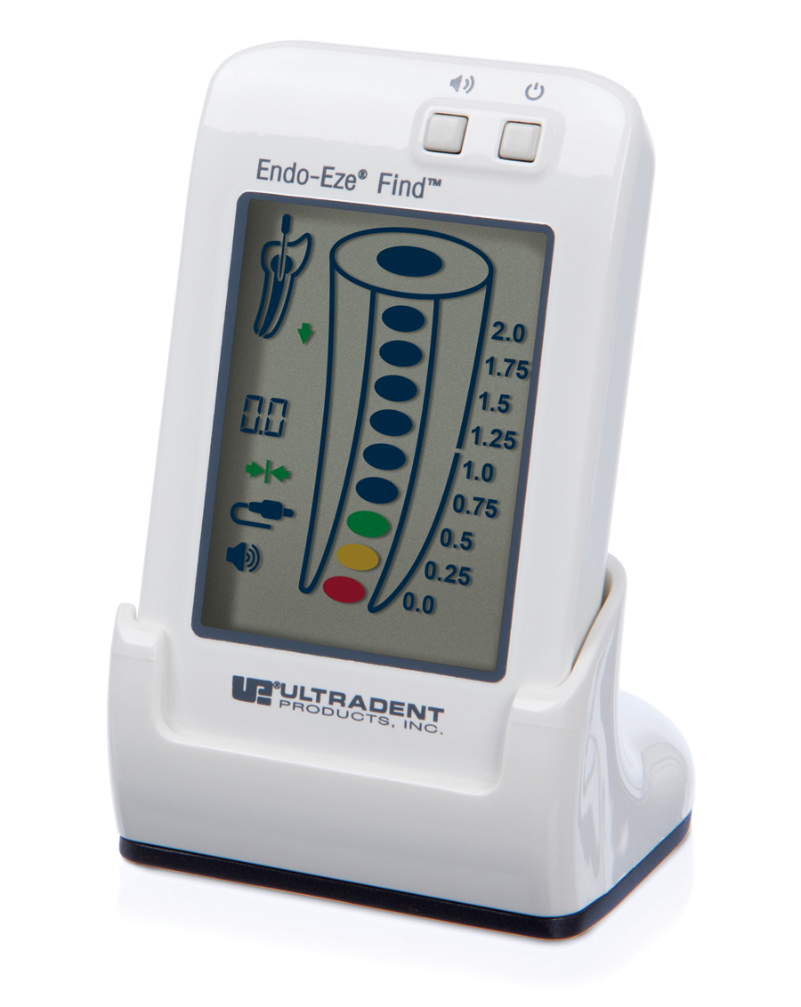
See Fig. 1.
FIGURE 1. Endo-Eze FIND Apex Locator (Ultradent, USA/Clinical Research Dental, London, ON)
Operative Sequence
• Turn on ![]() the device.
the device.
• Ensure that the measuring cable is properly connected. Cable symbol ![]() should appear after the connection (Fig. 2).
should appear after the connection (Fig. 2).
• Before placing the instrument inside the canal:
Create a contact between the electrodes (file clip and lip clip). The connection test symbol ![]() should appear, indicating proper connection (Fig. 2). Do not attempt to do the connection test using a file connected to the file clip and the lip clip.
should appear, indicating proper connection (Fig. 2). Do not attempt to do the connection test using a file connected to the file clip and the lip clip.
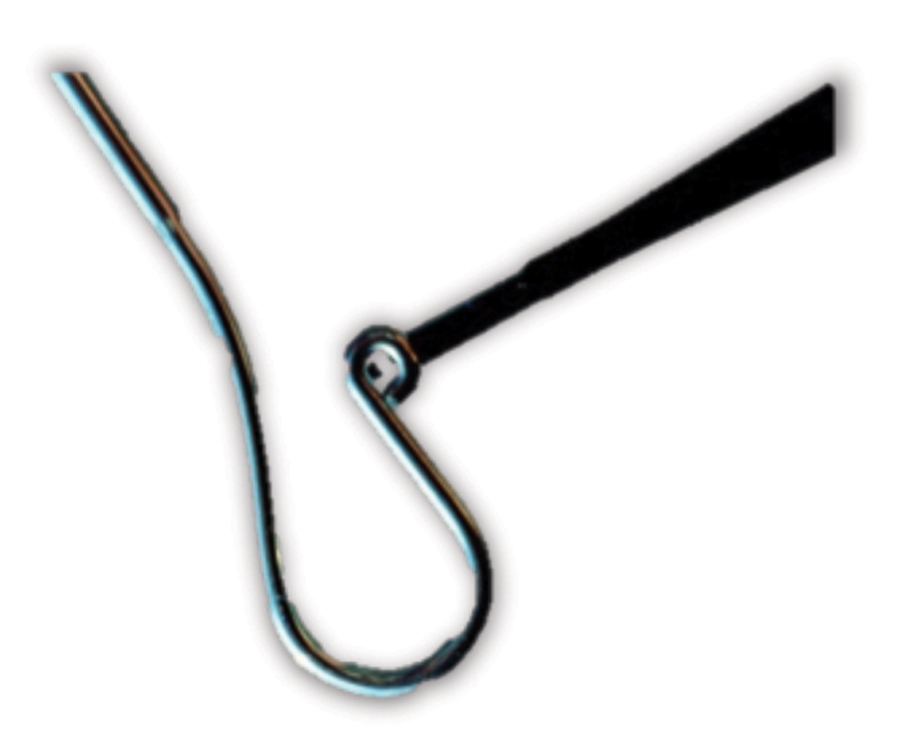
FIGURE 2. File clip and lip clip connected. Connection symbols: ![]() cable connected,
cable connected, ![]() connection test.
connection test.

✓ After access, verify that the tooth is isolated and that there are no metal restorations projecting into the canal entrances. Metal restorations divert the circuit, diminish impedance, and give a false-positive result.
• Vital pulp: A partial pulpectomy should be performed before electronic measurements. This must be limited to approximately 5 mm short of the temporary working length based on the X-ray image (Fig. 3). An instrument of a size that matches with the anatomic diameter of the apical third must be inserted without excessive apical pressure. The file clip of the device will now be connected to the instrument. Be sure there is no irrigation solution in the pulp chamber. Irrigation solution must be limited to the entrance(s) of the canal(s).
FIGURE 3.
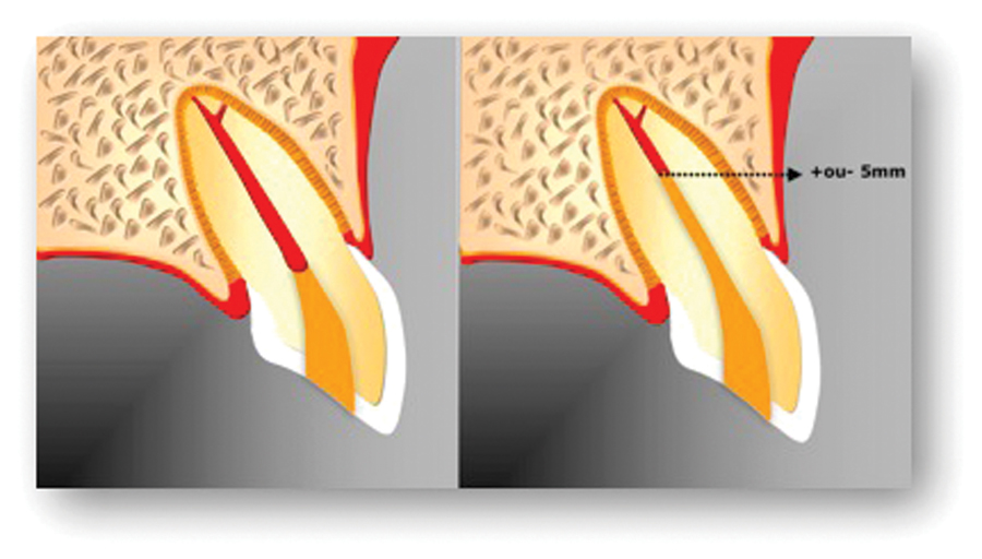
• Pulp necrosis: Sodium hypochlorite solution will promote initial cleaning of the necrotic remnants inside the pulp chamber. After the initial stage of progressive debridement, which is apically limited to a point 5 mm short of the radiographic apex (temporary working length) as measured on the X-ray – an instrument of a size that matches with the anatomic diameter of the apical third must be inserted without excessive apical pressure. The file clip of the device will now be connected to the instrument. Be sure there is no irrigation solution in the pulp chamber. Irrigation solution must be limited to the entrance(s) of the canal(s).
✓ Place the lip clip in the corner of the patient’s mouth.
✓ It is important that the canal contain an irrigation solution, while the pulp chamber should not contain an excess of solution.
✓ The endodontic instrument selected to explore the undebrided apical portion of the canal and associated electronic working length must be 5 mm longer than the temporary working length that was measured on the initial radiograph. It is necessary to have space available for placing the file clip between the rubber stop and the instrument cable.
✓ Ensure that the tip of the instrument is in contact with the internal walls. Very thin instruments may give a false-positive result. Use instruments of a diameter close to the anatomic apical third canal diameter.
✓ Introduce the file apically, turning it gently in a balanced force action. Observe the start of movement on the monitor, which will give the exact speed of penetration of the instrument into the canal in the direction of the apical foramen. The monitor of the Endo-Eze FIND apex locator is shown in Figs. 4–6.
FIGURE 4.
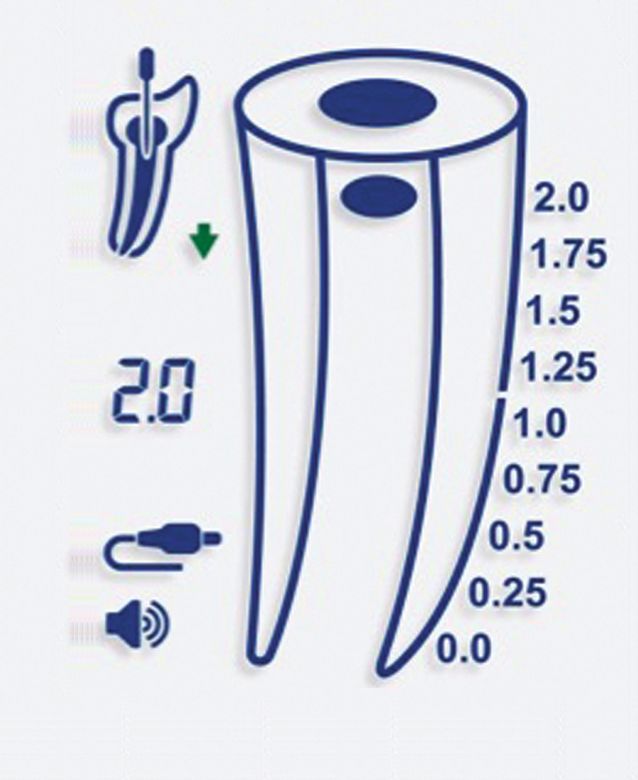
FIGURE 5.
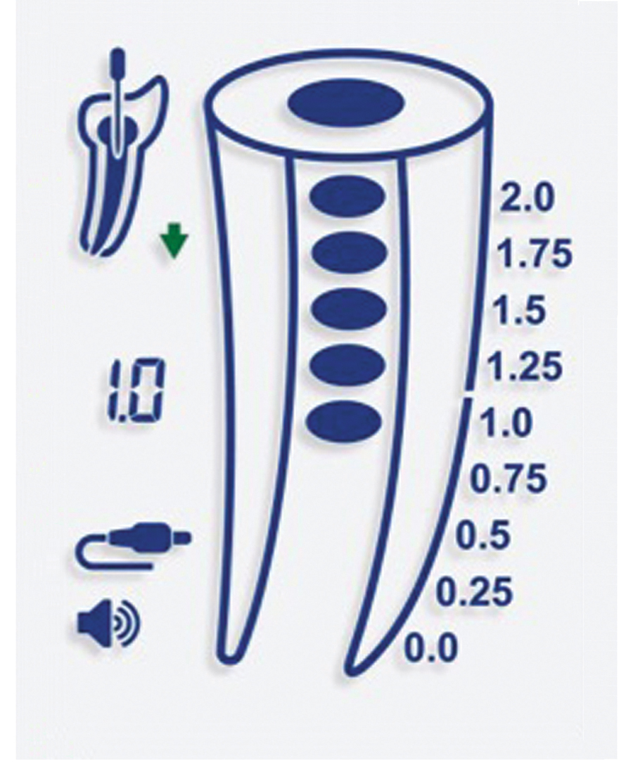
FIGURE 6.

✓ As the file nears the apex, an intermittent alarm sounds. Continue moving the instrument toward the apex until the alarm sound is continuous. This will place the read-out in the position of the major foramen exit (0.0).
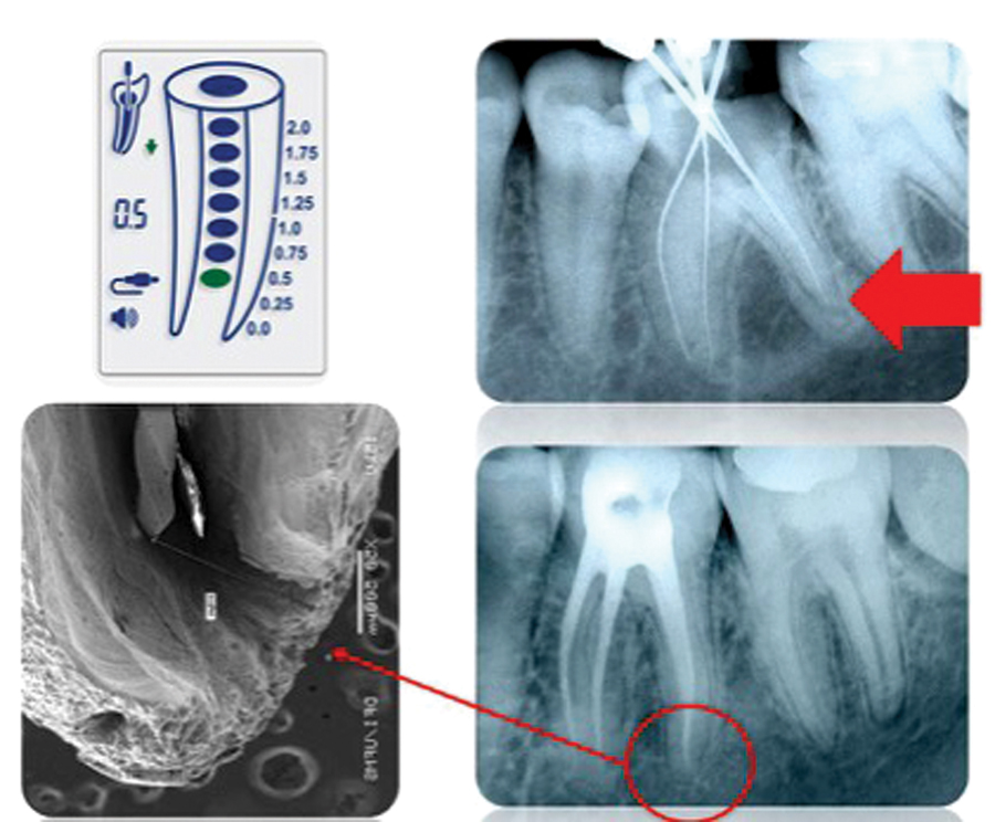
✓ Mark the shaping working length by sliding the rubber stop to the chosen occlusal or incisal reference point and subtracting 0.5 to one millimeter of the pointed measurement using an endodontic ruler. Optionally, the operator can withdraw the file until reaching the position 0.5 on the display as well.
✓ In some specific cases the foramen could be in a position that doesn’t allow the operator to insert the file until the exit. In this situation, the operator can stop at the point 0.5 and take an X-ray to confirm the position of the file related to the last apical millimeters (Fig. 7).
FIGURE 7.
Precautions During Electronic Measurements
Some points must be observed during electronic measuring regardless of the model of measuring device used:
✓ Metal crowns and large amalgam restorations causes a short circuit during electronic measurements. Remove the crown or the restoration before performing the procedure.
✓ Acquire a reliable diagnostic radiograph, preferably with the parallel technique, using an XCP System locator (in which the cone is lined up with a ring outside the mouth of the patient while the patient bites down on the X-ray holder). The real temporary working length measured from a proper initial radiograph normally differs from 0 to 15 percent26 from the definitive working length measurement.
✓ If the bar indicator on the display screen starts to oscillate up and down, remove the instrument from the canal. Irrigate, aspirate excess irrigation solution, turn off the device, and start the procedure again. Verify the presence of contact between the file and metal restorations (if present). Verify the presence of excess pulp tissue in case of an irreversible inflamed pulp. Verify that the battery is fully charged.
✓ The number of the instrument used for measurement must match with the anatomic diameter of the canal. Larger size instruments will not reach the apical third. Thin instruments make apical placement and reading difficult due to the lack of control over penetration.
✓ The intermediate numbers don’t reflect the actual position of the file related to the apical foramen. The accurate point is 0.0, which shows the foramen position.
Taking an X-Ray to Check the Electronic Measurement
One important aspect to bear in mind when using electronic working length techniques is the need for taking a radiograph to verify the accuracy of the method. In this regard, there may be a conflict of objective but not of procedure. The procedure of making a radiograph after electronic working length measurement must be performed even if the basic purpose of the procedure is not necessarily to confirm the accuracy of the apical limit established by the electronic reading. Studies have shown that the radiographic technique has minor and major limitations, depending on the root morphology of the tooth, the position in the arch, presence of anatomic structures that are superimposing the area of interest, and presence of apical resorption. Furthermore there are difficulties inherent to the making and processing of radiographs. Nevertheless, it should be pointed out that radiographs have to be made after electronic working length measurements in order to visualize the direction of the canal or canals. The image of an instrument in a canal facilitates identification of details concerning the angle and radius of curvature, arch length, dilacerations, and thickness of the dentin walls. It also offers a representation of the relationship of the tip of the instrument and the radiographic apex.
In this case, the radiograph with an instrument in situ shows details that can be used in addition to the details of the diagnostic image, allowing identification of situations that may necessitate different technical procedures. This step is valuable as it enables a novice operator to evaluate themselves regarding technical expertise, which will ultimately improve the operator’s confidence in using electronic working lengths measurements.OH
Oral Health welcomes this original article.
References
1. Burch, J. G.; Hulen, S. The relationship of the apical foramen to the anatomical apex of the tooth root. Oral Surg Oral Med Oral Pathol Oral Radiol Endod., v. 34, n. 2 , p. 262-8 , Aug. 1972.
2. Ramos, C. A. S. Influência do diâmetro do forame apical na precisão de leitura de um modelo de localizador apical eletrônico. Bauru, 1993. 117p. Dissertação (mestrado). Faculdade de Odontologia de Bauru–Universidade de São Paulo.
3. Harrison, J. W.; Baumgatner, J. C.; Svec, T. A. Incidence of pain associated with clinical factors during and after root canal therapy. Part 2. Postobturation pain. J. Endod., v.9, n. 10, p.434-8, Oct. 1983.
4. Swartz. D. B.; Skidmore, A. E.; Griffin JR., J. A. Twenty years of Endodontic success and failure. J Endod., v. 9, n. 5, p. 198-202, May 1983.
5. Glickman, G. N.; Mickel, A. K.; Levin, L. G.; Fouad, A. F.; Johnson, W. T. Glossary of Endodontic Terms. American Association of Endodontists, 7 ed., 2003.
6. Best, E. et al. A new method of tooth length determination for endodontic practice. Dent. Dig., v. 66, p. 450-4, 1960.
7. Bregman, R. C. A mathematical method of determining the length of a tooth for root canal treatment and filling. J. Canad. dent. Ass., v. 16, 305-6, 1950.
8. Ingle, J. I. Endodontics instruments and instrumentation. Dent. Clin. N. Amer., v. 1, p. 805-22, Nov. 1957.
9. Olson, A. K.; Goerig, A. C. ; Cavatio, R. E. The ability of the radiographic in determining the location of apical foramen. Int. Endod. J., v. 24, p. 28-31, 1991.
10. Ounsi, H. F.; Haddad, G. In vitro evaluation of reliability of the Endex electronic apex locator. J. Endod., v. 24, n. 2, p. 120-1, Feb. 1998.
11. Shabahang, S.; Goon, W. W. Y.; Gluskin, A. H. An in vivo evaluation of Root ZX electronic apex locator. J. Endod., v. 22, n. 11, p. 616-8, Nov. 1996.
12. Duinkerke, A. S. H.; Van Der Poel, A. C. M. An analysis of apparently identical radiographs. Oral Surg Oral Med Oral Pathol Oral Radiol Endod., v. 38, 962-7, 1974.
13. Tidmarsh, B. G.; Sherson, W.; Stalker, N. L. Establishing endodontic working length: a comparison of radiographic and electronic methods. N Z dent. J., v. 81, p. 93-6, 1985.
14. Lambriandis, T. Observer variations in radiographic evaluation of endodontic therapy. Endod. dent. Traumat., v. 1, p. 235-41, 1985.
15. Gutmann, J. L.; Leonard, J. E. Problem solving in endodontic working-length determination. Comp. Continuing Educ. Dent., v. 16, n. 3, p. 288-302, Mar. 1995.
16. Suzuki, K. Experimental study in iontophoresis. J. Jap. Stomat. Soc., v. 16, p. 414-17, 1942.
17. Sunada, I. New method for measuring the length of the root canal. J. Jap. Stomat. Soc., v. 25, p. 161-71, 1958.
18. Ramos, C. A. S.; Bramante, C. M. Instrumentação dos canais radiculares. In: ___. Endodontia. Fundamentos biológicos e clínicos. São Paulo, Santos Editora, 2001, Cap. 8, p. 159-206.
19. Gordon, M.P.J.; Chandler, N.P. Electronic apex locators. Int Endod J, vol. 37, 425-437, 2004.
20. Welk, A.R.; Baumgartner, J.C.; Marshall, J.G. An in vivo comparison of two frequency-based electronic apex locators. J. Endod., vol. 29, n. 8, p. 497-500, 2003.
21. Pratten, D. H.; McDonald, N. J. Comparison of radiographic and electronic working lengths. J. Endod., v. 22, n. 4, p.173-6, April 1996.
22. Dunlap, C. A. et al. An in vivo evaluation of an electronic apex locator that uses the ratio method in vital and necrotic canals. J. Endod., v. 24, n. 1, p. 48-50, Jan, 1998.
23. Lucena, C.M.; Robles, G.V.; Ferrer, L.C.M.; Navajas, R.M.J.M. In vitro evaluation of the accuracy of three electronic apex locators. J Endod, vol. 30, n. 4, p. 231-233, 2004.
24. Ramos, C. A. S. Avaliação “in vivo” da precisão de leitura de um modelo de localizador apical eletrônico. Bauru, 1998. 168p. Tese (doutorado). Faculdade de Odontologia de Bauru–Universidade de São Paulo.
25. Yamaoka, M.; Yamashita, Y. ; Saito, T. Electrical root canal measuring instrument based on a new principle–makes measurements possible in a wet root canals. Osada Product Information, n. 6, 12 p., June 1989.
26. Milano, No, N. F.; Silva, C. A. G. Comprimentos e distorções na condutometria em pré-molares e molares superiores e inferiores. Rev. Gaúcha Odont., v. 36, n. 2, p. 97-8, mar-abr, 1988.
Follow the Oral Health Group on Facebook, Instagram, Twitter and LinkedIn for the latest updates on news, clinical articles, practice management and more!


