

Introduction: Integrate ArduinoISP and Atmel Studio

Want a cheap solution, or even a spare solution for AVR programming? Worry no more, with this tutorial you will learn how to use an Arduino Uno as an AVR programmer that can be putted into action straight from the Atmel Studio 6.
In this tutorial we will be using the ArduinoISP sketch alonside with AVRDUDE and Atmel Studio to perform the full smooth integration between coding in Atmel Studio and deploying your code to your AVR microcontroller.
Step 1: Peparing Your Arduino
Since we will be using the Arduino Uno as an ISP programmer, we first have to upload a sketch that will be responsible for receiving data through the serial port (USART) and outputting it correctly to the target microcontroller through their SPI ports.
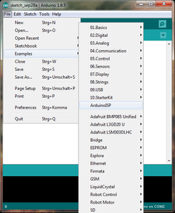
So, open up the Arduino IDE, go to File>Examples>ArduinoISP.
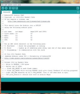
Once the sketch is open, on the top of the file, some comments are made on pin names and connections. Those will be addressed on the next step, but make sure they match with the tutorial.
Connect your arduino and fire the Upload button away. It takes a little more tha usual but don't worry.
Step 2: Connecting Your ArduinoISP Programmer to Your AVR
For this first step you will need the following materials:
- Jumper wires of saveral colors (yes they matter);
- 01 RED LED
- 01 YELLOW LED
- 02 LEDs of different colors, your choice (we are using blue and white)
- 01 10uF electrolytic capacitor
- 04 200 ohm 1/8W resistors
These other materials are project-dependent. In our case, we are going for a solution that uses a 8 MHz crystal and an internal clock with the same value. Therefore:
- 01 8 MHz crystal
- 02 20 pF ceramic capacitors
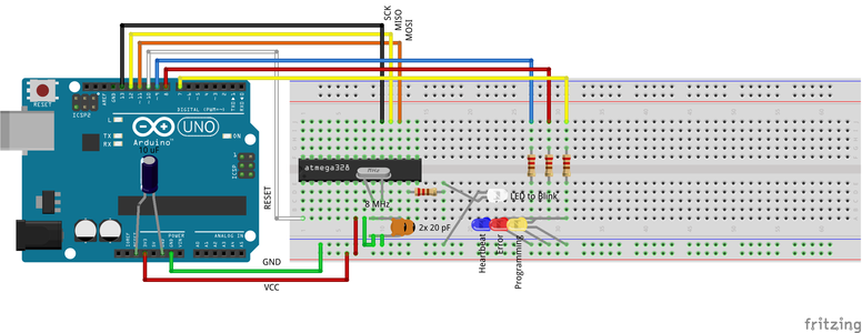
Hook all the components together according to the picture.
Do notice that for each trail that receives one of the lead of the crystal, there is a ceramic capacitor connecting this trail to the ground trail.
The LEDs' anodes are identified by the slight curve their leads have. Pay attention to the white LED, the one to be blinked by the code that will be loaded. Due to a software limitation, that doesn't allow component flipping, the LED ended up being crossed.
The electrolytic capacitor is polarized, therefore make sure you have the longer lead connected to RESET while the smaller one is connected to GND. This will filter out the automatic reset signal, disabling it.
A good advice is to keep the jumper wires in the same color code as the one shown in the picture. This helps further hardware debugging.
Step 3: Integrating Atmel Studio


Since you have used the Arduino IDE to load the ArduinoISP sketch to your Arduino board, this means that you already have AVRDUDE installed in your computer.
AVRDUDE is a command line application that intermediates the firmware loading process on your computer side. Long story short, AVRDUDE reads the .hex file produced by the compilation and translation process and queues it in order to output it correctly through the serial port. From there the USB-serial converter on your Uno board (the black square next to the USB port) reads it from the USB line, sends it to the ATMEGA on the Arduino Uno board and finally outputs it through SPI to the target microcontroller.
One of the coolest features of Atmel Studio is the support to external tools, like the AVRDUDE itself. Basically, Atmel Studio leaves this open enough to customization, that with the press of a button, you can perform a full command line program call and deploy your firmware to the target microcontroller.
Enough said,
Open Atmel Studio 6.
Go to Tools>External Tools
Fill in the fields as the picture shows. The Command field is to be filled with the location avrdude in your machine, in my case: C:\Program Files (x86)\Arduino\hardware\tools\avr\bin\avrdude.exe
As to the Arguments field, fill in with the following line:
-U lfuse:w:0xe6:m -U hfuse:w:0xd9:m -e -v -patmega328p -carduino -PCOM2 -b19200 -D -Uflash:w:"$(ProjectDir)Debug\$(ItemFileName).hex":i -C"C:\Program Files (x86)\Arduino\hardware\tools\avr\etc\avrdude.conf"
Those are the firmware deployment arguments or information to be interpreted by AVRDUDE and converted into write actions.
In this line there are three main things to be altered:
- The COM port you are using your Arduino Uno on. In order to check, go to Device Manager>COM&LPT Ports and you should see Arduino listed.
- The file path where to find avrdude.conf. A simple windows search should get you going with that.
- The fuse bits value, depending on how you have planned your projects configuration. Simply change the hex value in the middle of -U lfuse:w:0xe6:m and the fuse name you intend to configure.
Pay attention to the portion of the line with the .hex in the middle. That's the reference in the arguments to where AVRDUDE will look for the file. $(ProjectDir) and $(ItemFileName) are bash script variables and will be replaced according to your project name and location propely once the &Deploy action is called.
The other arguments are just guidelines to AVRDUDE concerning the target microcontroller and where to find the firmware file and the AVRDUDE configuration file.
Basically, this line of arguments makes AVRDUDE execute 4 write operations:
- The first writes the low fuse of the AVR
- The second, the high fuse
- The third operation is a full flash memory erase, as way to avoid write errors
- And the fourth a full flash memory write with the firmware
For a full list of arguments, go to : https://asensar.com/blog/2013/programming-arduino-using-avrdude/
Step 4: Compile It and Deploy It!


Once all the configuration is done, it's time to test it!
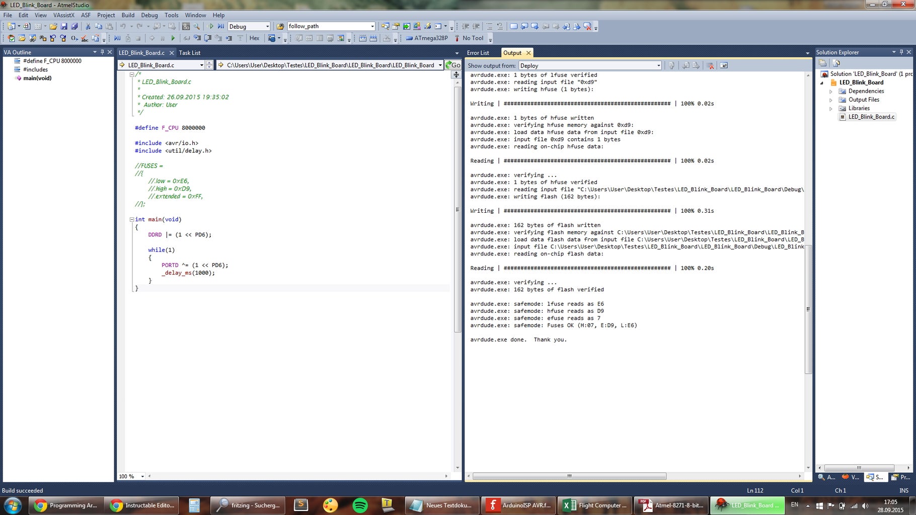
Write a simple LED blink firmware to your target microcontroller, like the one in the picture, and compile it.
Once it finishes, go to Tools>Deploy.
You should see something like the screen on the picture on the output window. That's an AVRDUDE verbosed output, telling you what it has executed.
First it shows some deployment info, then some memory stats, that really come in handy for larger projects, and finally it outputs the write operation summaries. Here you can observe 3 of the 4 writes that were mentioned before. The two fuses plus the flash.
Once this is complete you can already see your code working through your blinking LED! Congrats!
This configuration stays permanent for all your following projects, so don't mind having to do it all again. The one thing you might change from project to project is the fuses configuration that will have to be reconfigured on the arguments field of the previous step.
For the best fuse calculator, check: http://www.engbedded.com/fusecalc/
TROUBLESHOOTING:
It is possible that you run into AVRDUDE not being able to find or open your COM port. Should that happen, make sure you don't have your Arduino IDE open. This will cause AVRDUDE to try to claim the COM port while it is connected to the Arduino IDE. To solve that, close the Arduino IDE, disconnect the board from the computer, close Atmel Studio, reconnect the board, and then restart Atmel Studio 6.
I hope you have enjoyed it! Cheers!


