

Introduction: Smart Home Power Strip


Smart Home Power Strip is an android and/or iDevice controllable plug outlet. You can turn the individual outlets by taping a button from your gadgets. I spend about $32 making this project.
Difficulty level: Medium (Basic electronics and soldering skills required)
Time needed: A weekend
Disclaimer: This project involves voltages 110-220V which is dangerous. You must be very careful doing this work. Please do not proceed if you don't take safe measure while working with it. Make this at your own risk.
Step 1: Things You'll Need


You can buy these stuff from your local electronic store:
2 pin terminal block (x5)
Resistor 220 Ω (x4)
5V relay 5 pin (x4)
5mm LED (x4)
Blank PCB 2.5 inch x 4.5 inch or larger (x1)
Female Header 40 pin (x1)
Female-female jumper cables (x6)
fiber cable (2 meters)
You can buy these stuff from amazon or other online shop:
Arduino Pro Mini 5V (x1)
FT232RL FTDI USB to TTL Serial Adapter Module (x1)
You can buy these stuff from your local chemical store:
H2O2 500ml (x1)
HCl 500ml (x1)
**You can buy these from your local hardware store:
M. 3 X 60 Screw (x4)
M. 3 P0.50 Nut (x8)
M5 X 20 Spacer (x8)
2mm acrylic sheet (x1)
4 plug outlet electric socket*** (x1)
You can recycle from your used phone charger:
DC Power Supply (will be explained more in step 4)
*You must use HM-10 if you want to use iDevices
**You can replace all the materials here with a prototyping box except for the electric socket
***The electric socket must have a switch for each plug outlet
Step 2: Making/Etching Your PCB


- Cut your PCB board to 6.7cm x 12cm.
- Print the PCB design using laser printer on a glossy paper.
- Place the paper with the PCB board.
- Press using an iron or a laminator.
- Etch the PCB
I used Hydrochloric acid + Hydrogen peroxide to etch my PCB. I'm not going to explain this step in detail, but you can check this instructable (not mine) if you never etch your own PCB.
Attachments

Step 3: Drill the PCB and Solder the Electronic Components


- Using a mini drill, drill all the holes on your PCB, I recommend using 0.8mm or 1mm drill bit.
- After you finish drilling you should solder all the electronic components, header pin, and some jumper cables.
Soldering small electronic components to a PCB can be quite frustrating for beginners. Here is a guide to soldering: https://www.instructables.com/id/How-to-solder/
Step 4: Finding the Right Power Supply for Arduino


- You can find the power supply from your old phone charger or from other power supply unit.
- The power supply should have 5V Voltage output. The current can be 750mA or even better if you have 1000mA.
- Use a saw to open the Power Supply enclosure.
Step 5: Plug Your Arduino Pro Mini and Bluetooth Module to the PCB


Before placing the bluetooth module, you should bend the pins first.
- Bend the pins one by one using pliers. Be careful not to break the pins (I accidentally broke mine).
- Plug the Arduino Pro Mini and bluetooth module to the female header.
Step 6: Programming Your Arduino


- Connect your Arduino to your computer using USB to TTL.
- Upload the arduino code.
Attachments

Step 7: Hacking the Electric Socket and Power Supply


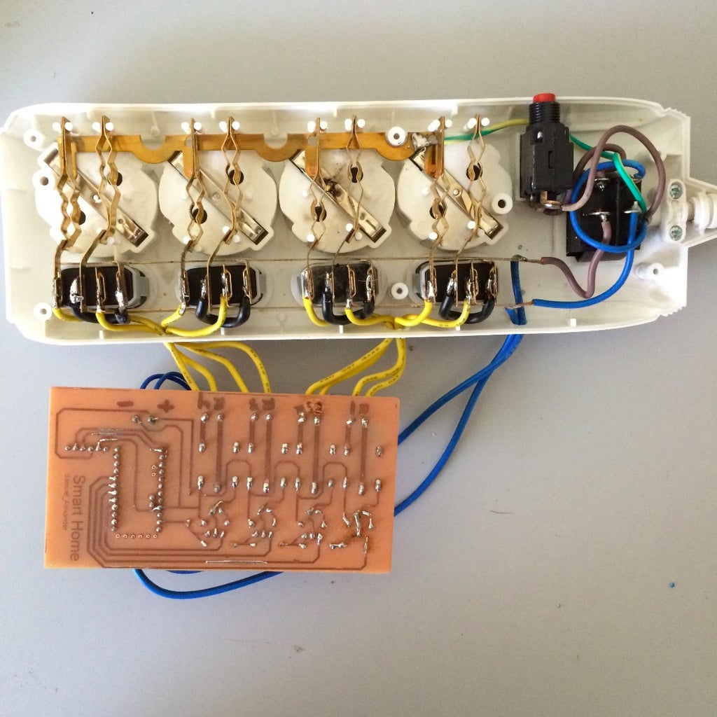


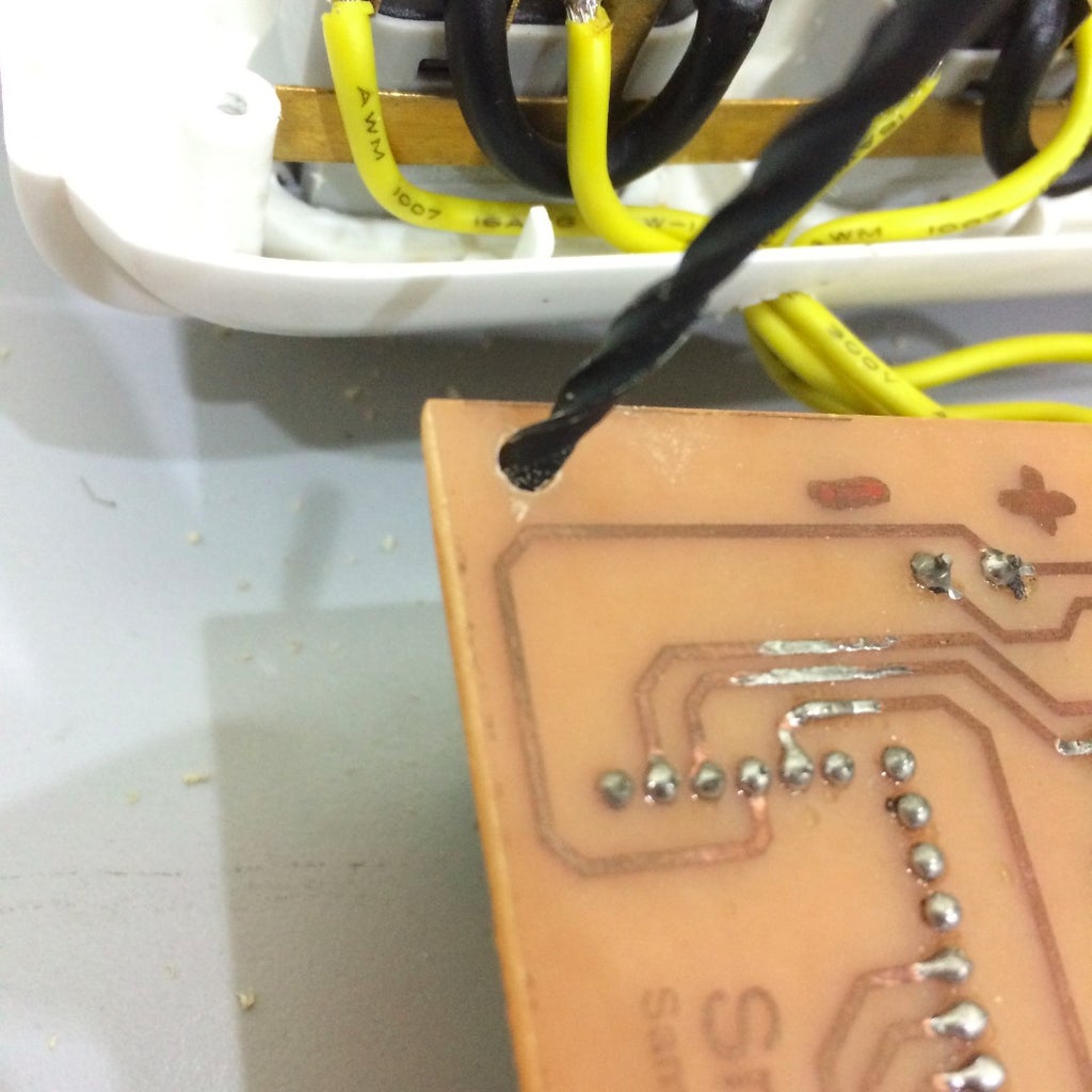
- Open the electric socket screws. The relay from your PCB will not replace the function of the switch from the electric socket. In my picture, when the switch is on, the pins (the one I drew with a line) will be connected. If you connect the two pins from the AC input, there will be a short circuit (That's dangerous), so you cannot connect those pins. You can solder one of the pins directly to the output as shown in the next picture.
- Next, you'll need to drill 2 holes (between 1st and 2nd switch and between 3rd and 4th switch) for the cables to go out from the electric socket. solder the remaining pins to a cable, and connect it to the terminal block on your PCB (Please be careful not too screw the cables to the wrong place).
- Drill one more hole and solder a cable to each pin from the 220V input. Solder the cables to the power supply input. Solder two cables to the power supply output and screw them to the terminal block to power the Arduino. Screw the positive pin from the power supply to the positive terminal block. Screw the negative pin from the power supply to the negative terminal block.
- Don't forget to screw back the electric socket.
Step 8: Making the Enclosure


Steps to make acrylic enclosure:
- Laser cut your acrylic using the given .eps file
- Insert four screws to the acrylic holes.
- Tighten the screws using nut. Use the screws from the acrylic and mark the PCB (The curvy part near the relay terminal block and the other cut part near the bluetooth module).
- Drill the holes on the marked PCB.
- Insert the screws to the holes.
- Insert nut and a spacer to each screws.
- Insert another acrylic and tape the power supply to the acrylic.
- Follow the same pattern. Your enclosure should look like mine.
Using this acrylic enclosure, the project will not be fully enclosed. This project involves high voltages, for safety reasons it is highly recommended to use a fully enclosed case. Only use the acrylic enclosure if you are sure about all the electronics connections.
If you want to use fully enclosed case, you'll need to find a prototyping box with suitable size and drill holes for the cables.
Attachments
Step 9: Using Your Android Device

- Download the app: Arduino Bluetooth Controller.
- Connect/pair your Android device to your bluetooth module.
- Open the app
- Open terminal
- *Press 1 to turn on switch one, press 2 to turn on switch two, and so on...
- *Press 5 to turn off switch one, press 6 to turn off switch two, and so on...
*Press enter after you press the number, you can turn on/off several switches at once.
Step 10: Bonus Mod Ideas

- More relays
- Voice activated
- Control over wifi
- Sensors
Have fun ;)

First Prize in the
Home Automation

Participated in the
Before and After Contest

Participated in the
Bedroom Contest


